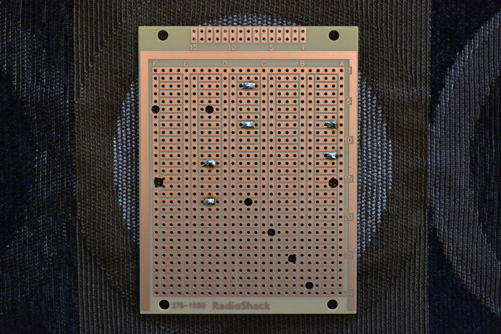
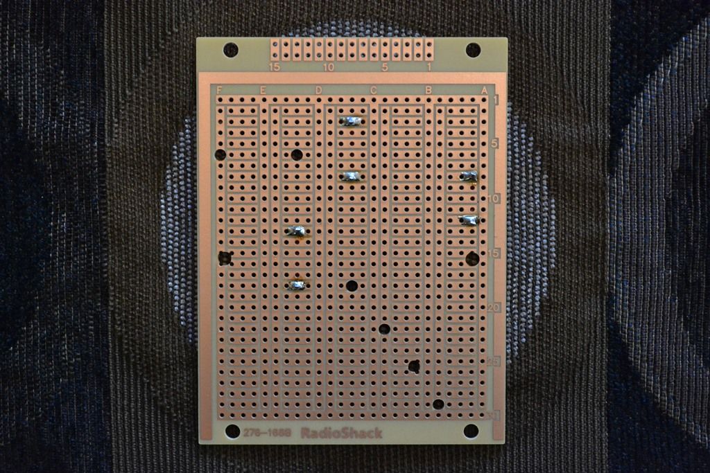
If it will help clear up your confusion, here is a photo of the back of one of the Radio Shack perf boards with the red jumper wires soldered in place (no components mounted on the board):
And here's some more info on the connection of the IN+ lead:
As shown in the schematic and described in the text, that is the original lead that connects directly to the + input terminal on the speaker cup.
It does not connect to the original crossover PCB at any location.
It connects directly from the + input terminal on the speaker cup to location D3,29 on the Radio Shack perf board, as shown in Table 4.
As shown in Photos 6 and 7, there is no wire connected to the IN+ via on the original crossover PCB. Here is the text that accompanies those photos:
"
You will also need to remove the IN+ lead (red wire) from the PCB and pull it apart from the IN- lead. Set it aside for reuse.
At this point, the only items remaining attached to the original crossover PCB are L1, R1 the W+/W- leads and the IN- lead."
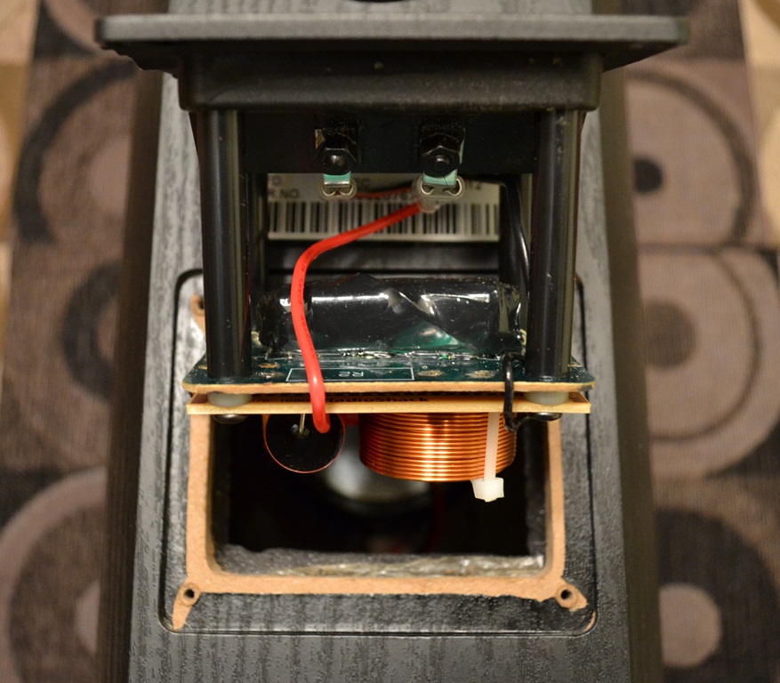
And, here's a photo that shows that wire connected between the speaker cup and the Radio Shack perf board:
Hope that clears up any confusion.


 everithing worked
  , Im trying to find out how to post the pictures of my work, as soon as I find out Ill be posting some


