Suggestions for unknown capacitors

Shane Nudds

New Member
Picked up a pair of Jensen 3-P/2 super slim panel speakers from 1961. They work but obviously the caps are dried out. Removed them from the first speaker hoping the paper would have some specs on it but nothing. Can't find anything online either (specs, schematics). How do you go about replacing caps when you dont know the original values? Thanks in advance
 

Attachments

  • 20180113_114833_001.jpg
    20180113_114833_001.jpg
    62.6 KB · Views: 76
  • 20180113_123320.jpg
    20180113_123320.jpg
    92.5 KB · Views: 73
  • 20180113_120428.jpg
    20180113_120428.jpg
    90.8 KB · Views: 77
I don't see any inductors (coils), just capacitors -- is that right?
I am assuming that the are four drivers in toto, and the XOs are ultra-simple/ultra-cheap first order "high-pass" XOs to the three smaller drivers, with the woofer "running free" -- is that in fact the case?

If so, for 8 ohm drivers, the XOs would be:

600 Hz 33 uF
4000 Hz 5 uF
10000 Hz 2 uF

In terms of quality - don't over invest in capacitors ;)

modern NP electrolytics would be OK and cheap:
https://www.parts-express.com/cat/non-polarized-electrolytic-capacitors/1385

You could certainly do better caps if you wanted to, but, investment-wise, the 4k and 10k sections are probably the only places worth it.
I'd opine that something like these would be more than adequate quality.
https://www.parts-express.com/cat/crossover-capacitors/292?N=19841+4294967118+4294967060&Ne=10166&Nrs=collection()/record[endeca:matches(.,"P_PortalID","1")+and+endeca:matches(.,"P_Searchable","1")]&PortalID=1

If you cannot find the exact value capacitor - for speakers like these, close enough is probably close enough -- or you can combine two capacitors in parallel (capacitances in parallel are additive -- thus a 4.0 uF plus a 1.0 uF capacitor wired [EDIT] in parallel presents a net capacitance of 5.0 uF.

Do you know that the drivers (individual speakers) all work?
 
Last edited:
1. Welcome to AK, Shane!

2. Good work, Mr. Hardy! You are right on the money, sir. ;)

3. Curious as to what these look like, but can't find images anywhere.

GeeDeeEmm
 
Thanks for all the replies. There are 5 speakers total. Ohm'd the wires to see what speakers the capasitors were driving. The wires are labeled as follows

Woofer= LF
Mid= MF
2 outer tweets= HF
Middle tweet= UF

Each has a green and yellow wire going to them. Here is what I found

HF#1 green and yellow going to small cap.
HF#2 green and yellow going to small cap.
UF green going to small cap
LF green and yellow going to both big and small caps
MF green and yellow going to cap, green also going to small cap.

Does that help at all?
 

Attachments

  • 20180114_154729.jpg
    20180114_154729.jpg
    89.2 KB · Views: 28
Thanks for all the replies. There are 5 speakers total. Ohm'd the wires to see what speakers the capasitors were driving. The wires are labeled as follows

Woofer= LF
Mid= MF
2 outer tweets= HF
Middle tweet= UF

Each has a green and yellow wire going to them. Here is what I found

HF#1 green and yellow going to small cap.
HF#2 green and yellow going to small cap.
UF green going to small cap
LF green and yellow going to both big and small caps
MF green and yellow going to cap, green also going to small cap.

Does that help at all?

Are there only two capacitors ("small" and "big")?
If so, do (did) they have more than two wires on each? (They might be "multisection" capacitors...?)

a priori, I have no idea what's going on based on your description -- other than that green and yellow wires presumably map to the + (or "hot") and - (or "gnd") speaker terminals. Sorry!

ALSO: A kind AK member pointed out to me that I'd made an error in my original post to this thread -- which I just went back and fixed.
 
Thanks for all the help so far. I am out of my element a bit. I tried Jensen directly but they keep passing me around. One email gave me a link to their marine division haha. Can anyone give me a list of what I should order?
 
Here is the other speaker that I have not taken a part yet. Everything seems to be working but the sounds just kind of fall over each other. definitely needs new capacitors to get all the frequencies pointed in the right direction. Just sat it at the table real quick so excuse the horrible setting

 
Thanks for all the help so far. I am out of my element a bit. I tried Jensen directly but they keep passing me around. One email gave me a link to their marine division haha. Can anyone give me a list of what I should order?
Yeah, there's no hope there -- Jensen's just a trade name at this point.
 
No idea based on the wiring info you provided.
Not sure what to suggest.
If you crack open the other loudspeaker and take some photos of the crossovers in situ with the wiring labeled on the photo as to which drivers are connected to what, maybe...

Alternatively, if you have the moxie :) to draw a diagram of the wired crossovers - as best you can - that might help us suss it out.
Your written description a few posts back completely flummoxed me.

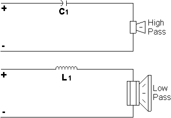
Generally speaking a first-order (capacitor) crossover -- a "high pass" crossover -- is wired like this, with the capacitor in series with one of the speaker driver's two terminals (the top example in the borrowed figure above):

calc_cr_06db.gif


I cannot understand the description of the wiring you described earlier, sorry.

Thanks for all the replies. There are 5 speakers total. Ohm'd the wires to see what speakers the capasitors were driving. The wires are labeled as follows

Woofer= LF
Mid= MF
2 outer tweets= HF
Middle tweet= UF

Each has a green and yellow wire going to them. Here is what I found

HF#1 green and yellow going to small cap.
HF#2 green and yellow going to small cap.
UF green going to small cap
LF green and yellow going to both big and small caps
MF green and yellow going to cap, green also going to small cap.

Does that help at all?
 
No idea based on the wiring info you provided.
Not sure what to suggest.
If you crack open the other loudspeaker and take some photos of the crossovers in situ with the wiring labeled on the photo as to which drivers are connected to what, maybe...

Alternatively, if you have the moxie :) to draw a diagram of the wired crossovers - as best you can - that might help us suss it out.
Your written description a few posts back completely flummoxed me.

Generally speaking a first-order (capacitor) crossover -- a "high pass" crossover -- is wired like this, with the capacitor in series with one of the speaker driver's two terminals (the top example in the borrowed figure above):

calc_cr_06db.gif


I cannot understand the description of the wiring you described earlier, sorry.


Here are some pics of the other speaker. This one doesn't have near as much silicon in it so I was able to tell that there is a coil under everything. In reference the top 2 brown speakers are labeled HF, top middle is UF, middle speaker is MF and bottom is LF. Yellows go to positive and green to ground. My previous message is what I found when checking co20180116_210108.jpg ntinuity from each speaker wire to each lead of capacitors. The second pic you can see what I was calling big cap and small cap. Last picture is HF adjuster that ia also wired into the crossover. Are there any other pics or details that would help? 20180116_210108.jpg
 

Attachments

  • 20180116_210527.jpg
    20180116_210527.jpg
    48.1 KB · Views: 11
  • 20180116_210138.jpg
    20180116_210138.jpg
    52.2 KB · Views: 10
You need to trace out how the wires are connected before you rip the second speaker apart. My suspicion is that the woofer has no crossover and rolls off mechanically with the single coil being on the midrange. Next guess would be that the (2) identical tweeters are in parallel and connect to one capaciator. Where they roll-off the single tweeter comes in and it is connected to the other capacitor. I'm guessing though.

Question: Does the remaining speaker play and is there output from any of the (3) tweeters? If so, put some music on and let it play for a few hours. While you are doing that get on ebay and look for a Chinese DVM that will measure capacitance. There cheap and will do much more to get you towards your goal.

All the wires have been traced. I posted a PDF that shows where they go. They were traced using continuity
 
Back
Top Bottom