Replacing AU-X1 F-2772 Phono Mother Board

Hyperion

Roobarb & Custard
Subscriber
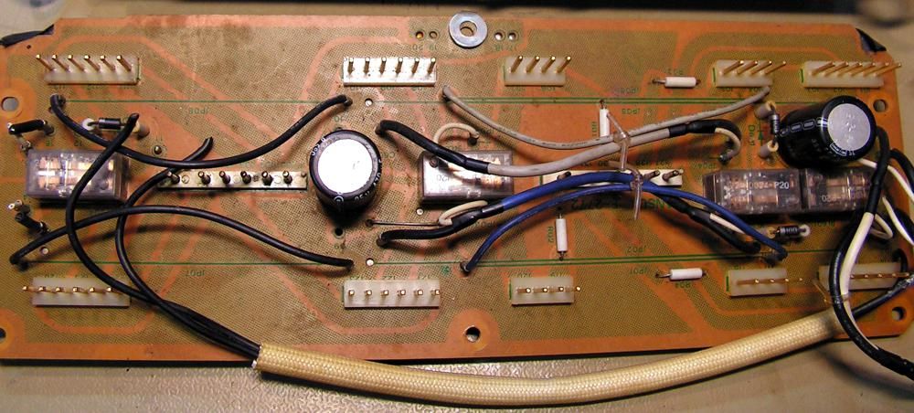
Original Mk2 Phono Mother Board - with replacement relays
IMG_2425.JPG
Side view.
IMG_2426.JPG

New board fully rebuilt.
IMG_2427.JPG
Old board - Empty!
IMG_2428.JPG

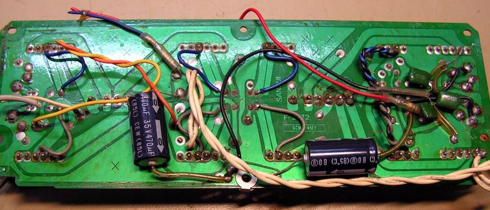
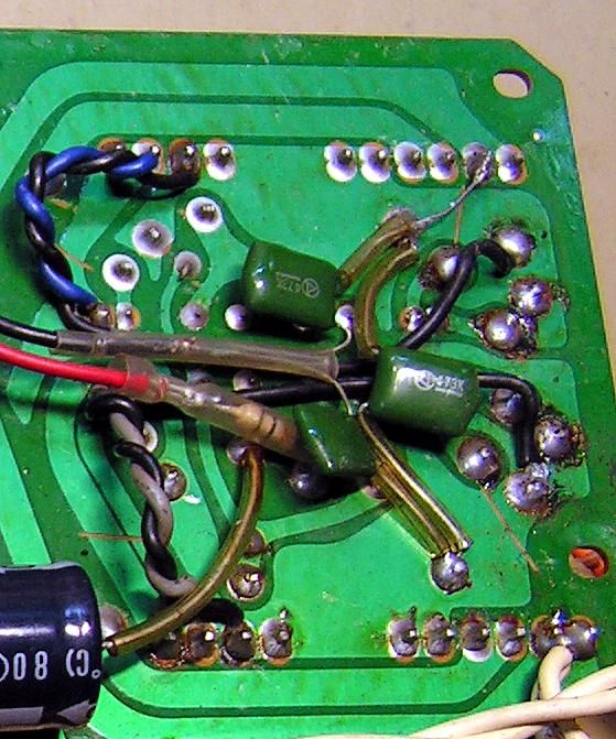
There are just 2 (carbon film) resistors on this board, a 33Ω and a 5.6Ω - the 5.6Ω had drifted to 7.4Ω so it was replaced, along with the 33Ω for completeness.

The new board is beautiful, a top quality replacement designed by AK's own Ronito6. This is particularly for anyone with a Mk1 board, which has a bewildering array of factory modifications to make it stable. But also for anyone with a Mk2 board wishing to rationalise the mounting of the much needed replacement signal relays which have a different PCB 'footprint' compared to the old unreliable relays. Ron was also significantly helped by AK member Willy6 with installation testing & tweaks and ordering boards from the US based PCB fabricator.

The topside silk screening has been much enhanced by indicating the colours of the connecting wiring, making it a very easy job to wire back into the unit.
 
Last edited:
It's great to get a clone of a board, and very laborious. It would be ideal to find a clone of the F-5693 card of the Sansui X-701/901. It is a board very delicate to the temperature, I have one with several tracks raised. I looked at methods to make it new but it is very very difficult. You have done a great job.
 
Thanks for the thumbs up on my 2772 Hyperion.

In case anyone cares or is wondering...
Willy6 asked me, wondering if I could make this board a reality. And since he and I are the same in our "What the hell. Why not give it a shot." attitude. I gave it a shot. And it worked.

Might a parts list be offered please?
I got 4 or 5 guys here on AK who will likely be referencing this thread rather soon as they install these new boards. I am sure they will appreciate that bit of detail from a real EE guy, rather than my amateur best guesses.

I guess the big Q for me here is: Is there any difference / improvement sonic-ally?

Is there an O scope test to show?

Oh...BTW...one of the two holes I designed into this board's star ground point is intended for the Kuehne flat amp stability modification.

I am rather sputtering now. (Not unusual for me, but ....I'll just stop here.)

Looks good that board in your hands!

Thanks for installing it!

Ron
 
Might a parts list be offered please?
I got 4 or 5 guys here on AK who will likely be referencing this thread rather soon as they install these new boards. I am sure they will appreciate that bit of detail from a real EE guy, rather than my amateur best guesses.
I'll see if I can put something together - I can see this would be useful for someone upgrading a Mk1 board by replacing it with a new board.
I guess the big Q for me here is: Is there any difference / improvement sonic-ally?
No difference sonically, except maybe a small reduction in random noise pickup. If there is a reduction, it will be due to being able to mount the signal relays directly on the board.
Is there an O scope test to show?
No, nothing really of interest to see.
Oh...BTW...one of the two holes I designed into this board's star ground point is intended for the Kuehne flat amp stability modification.
I simply used the existing solder tag for this - but this may not be present on earlier X1 models maybe those with the Mk1 board?
I am rather sputtering now. (Not unusual for me, but ....I'll just stop here.)

LOL - you're doing fine. :thumbsup:
 
Last edited:
AU-X1 Phono Mother Board Parts list (refers to new upgrade board or Mk2 board)

6 x Omron G5V-2-DC24 signal relays.
1 x 33Ω ¼ watt resistor.
1 x 5.6Ω ¼ watt resistor.
3 x 1N4003 rectifier diode. (replacing 10D1)
4 x 470µF 35V electrolytic capacitors. (I used 63V here)
2 x 0.047µF 100V film capacitors.
1 x 0.27µF 100V film capacitor.

 
Last edited:
AU-X1 Phono Mother Board Parts list (refers to new upgrade board or Mk2 board)

6 x Omron G5V-2-DC24 signal relays
1 x 33Ω ¼ watt resistor
1 x 5.6Ω ¼ watt resistor
3 x 1N4003
4 x 470µF 35V Electrolytic capacitors (I used 63V here)
2 x 0.047µF 100V film capacitors
1 x 0.068µF 100V film capacitor (unsure of value)
Thanks!

As I remember everything in terms of caps was some factor of 47.

BUT it seems to work well enough.

:banana::banana::banana:
 
Found it - it was 0.27µF or '274K' - corrected in post above. ;)

The one thing I do notice is that I can just hear the relays now - suspended in mid air by the corrective wiring they just made a hard to hear faint click - but now it is more of a definite louder click amplified by the stiffness of the PCB. :)
 
Last edited:
the Kuehne flat amp stability modification
Sorry to be a muppet from downunder but is there a link to this mod?

I'm still not sure if I have the Mk1 or Mk2 board in my unit (Kevzep may know). I wont know for sure until I get in there to install this new board.
 
Sorry to be a muppet from downunder but is there a link to this mod?

I'm still not sure if I have the Mk1 or Mk2 board in my unit (Kevzep may know). I wont know for sure until I get in there to install this new board.

In Germany, an EE guy by the name of Martin Kuehne discovered that the main source of the AU-X1's famous destructive oscillation originated in the grounding scheme of the AU-X1's F-2819 flat amp. http://ftbw.de/xp/amplifier-xp/sansui-au-x1-01.html

So Mr. Kuenhe sussed out how to correct that flaw, and a couple of other flaws in the X1 in order to make is as stable and reliable as any other amp.

Mr. Kuehne's solutions are very easy to apply. They are a must as far as I am concerned.

Before his contribution, people tackling the issue of the AU-X1's oscillation would suggest cutting out or re-routing whole areas of the amplifier's diamond differential circuitry. Crazy. :no::crazy::no:

Harolda discusses finding Mr Kuehne's discovery here
http://audiokarma.org/forums/index.php?threads/the-mighty-au-x1.672322/page-8
See posting #144

Mr. Kuehne himself discusses his work here http://audiokarma.org/forums/index.php?threads/the-mighty-au-x1.672322/page-8
See posting #157 to #161.

For the first time on AK, Harolda describes and applies Mr. Kuehe's flat amp modification here
http://audiokarma.org/forums/index....-output-transistor-replacements.684619/page-8
See posting #151 to #155.

For the first time on AK, Hyperion describes and applies Mr. Kuehne's DC drift fix for the EQ cards F-2770 and F-2771 here http://audiokarma.org/forums/index.php?threads/the-mighty-au-x1.672322/page-10
See posting #182 to #194.

ACTUALLY this last site above and it's suggested postings rather sums up the whole slew Mr. Kuehne's modifications in pictures.

Enjoy!:thumbsup:


Ron
 
Last edited:
Mk1 or Mk2

Just from this pic I can tell you that you certainly have a version 1 ( Mk1).
This is yours yes??
index.php


Mk1 ( From Martin Kuehne's website http://ftbw.de/xp/amplifier-xp/sansui-au-x1-01.html )

upload_2018-8-13_14-6-21.png

Mk1 from Kale's restorations
http://audiokarma.org/forums/index....o-export-model-plus-restoration.477461/page-4

PICT0883.jpg
PICT0884.jpg


PICT0884_.jpg


Mk 2 from Amp8's site http://topseller.jp/store/member/amp8/sansui/x-xx/au-x1-8.htm
x1-8-x.jpg

x1-8-b.jpg
 
Nice - thanks Ron - so I must have posted pics of my board on a previous X1 thread.

I will need to read up on this stuff!
 
Thanks @Ronito6 - my board is all installed - aint it purty?! It only took me, 4 years or so to do this......

The labelling on the board was great and I was easily able to track down all the correct connections to the correct places. I also had to cut the wires from one 6-pin power connector and solder these directly into the PCB as shown.

I only had one question - underneath, where the blue & red wires connect - they do so via a resistor at the end of the wire. I am assuming that these resistors remain in place (as pictured?) cheers!

IMG_3360.jpg IMG_3361.jpg IMG_3362.jpg
 
Thanks @Ronito6 - my board is all installed - aint it purty?! It only took me, 4 years or so to do this......

The labelling on the board was great and I was easily able to track down all the correct connections to the correct places. I also had to cut the wires from one 6-pin power connector and solder these directly into the PCB as shown.

I only had one question - underneath, where the blue & red wires connect - they do so via a resistor at the end of the wire. I am assuming that these resistors remain in place (as pictured?) cheers!

View attachment 2397693 View attachment 2397694 View attachment 2397695

Proud tech papa here.

The resistors where dropped in the Sansui second version of the board. So you can remove them.

Allow me to double check though. Just a sec.
 
Yep. 86 those resistors. (Need to add that to the procedures list. Thanks!)

Here is a pic that shows the bottom of a 2772 from an X1 with an original factory 2772 version 2 board.

(For anyone interested, I designed my 2772 after the original Sansui 2772 version 2. Mine will take modern relays.)
(Installing nmine into an X1 that came with a 2772 version 1 is possible, but a bit trickier.)
(I really must design one that is version 1 friendlier. I will…eventually.)

Here is a pic of the underside of a Sansui made 2772 version 2 before removal from the unit.
upload_2021-11-19_10-59-57.jpeg
Proud tech papa here.

The resistors where dropped in the Sansui second version of the board. So you can remove them.

Allow me to double check though. Just a sec.
.
 
Last edited:
I am glad I got the 919 because all these problems would be out of reach for me to deal with it.
I did my 919 myself.

The X1 has summoned the creativity and skills of an army of people who know and agree on one thing, the X1 is worth the effort. At the end of the process you will possess one of the best sounding amps ever made.

Building skills and ending up with a world-class amp, that is a double win in my book.

It’s like one of those cars you “have to drive before you die”, if you are given the chance.
 
Last edited:
Thanks @Ronito6 - my board is all installed - aint it purty?! It only took me, 4 years or so to do this......

View attachment 2397693 View attachment 2397694 View attachment 2397695

Nice!! Slow and steady wins the race but oh gosh, be forewarned...the phono stage on the X1 sounds amazing. I drifted away from vinyl decades ago but this thing sent me down the vinyl rabbit hole and I've barely come up for air since! Years later I still shake my head in amazement.
 
Last edited:
Thanks for that Ron, I will remove those resistors in that case.

Vintagear - Im looking forward to hearing the phono stage - my X1 is now actually boxed up and ready to go to Kevzep - I want him to boot up the phono boards and get them working, plus try to find my missing channel, the problem is somewhere around the volume control.

Cheers!
 
Nice!! Slow and steady wins the race but oh gosh, be forewarned...the phono stage on the X1 sounds amazing. I drifted away from vinyl decades ago but this thing sent me down the vinyl rabbit hole and I've barely come up for air since! Years later I still shake my head in amazement.

I agree. The X1’s phono stage is indeed really amazing.
 
Back
Top Bottom