
I got this amp and I replaced a few resistors that were wrong from someone else so both boards are correct and identical and the caps on the control boards too. One control board after turning on lights up the normal led and the clip led stays on and the output relay closes. It does this for either amp module it’s hooked to. The other control board after turning on lights up the normal led, the clip led goes off and the relay closes. Then after 30 seconds the relay starts to open and close constantly along with the clip led lighting up and off. It does this for either amp module it’s hooked to. I’m not sure what to look for to figure this out. Should I check all the output devices to see if any show bad, there’s 14 per module. The only thing I have is the circuit drawing from the JBL site.

You are using an out of date browser. It may not display this or other websites correctly.
You should upgrade or use an alternative browser.
You should upgrade or use an alternative browser.
UREI 6500 issues
- Thread starter hamrules
- Start date
A link would be handy.The only thing I have is the circuit drawing from the JBL site.
Does this channel work?One control board after turning on lights up the normal led and the clip led stays on and the output relay closes.
Was this amp working or non-working before you started?I got this amp and I replaced a few resistors that were wrong from someone else so both boards are correct and identical and the caps on the control boards too.
I have not hooked it up to a speaker but it does show 12.8mv DC offset at the speaker terminal.Does this channel work?
I bought it and they said it was working but i'm doubtful it really was. I did not actually try it first, maybe I should have.Was this amp working or non-working before you started?
Thats hardly any DC offset.I have not hooked it up to a speaker but it does show 12.8mv DC offset at the speaker terminal.

If I move the control board to the other amp channel then it does this identical thing and has 13.0mv DC offset at the speaker terminal.I have not hooked it up to a speaker but it does show 12.8mv DC offset at the speaker terminal.
I will shoot some pics and get them up later on.Can you post photos of the parts you replaced on the channel that the relay toggles on and off ?
Guess that narrows it down to the control board.If I move the control board to the other amp channel then it does this identical thing and has 13.0mv DC offset at the speaker terminal.


1st is an amp board
2nd is a control board
3rd is the other control board
I didn't take a pic of the other amp board
I was checking the resistors and there seems to be a huge variance in readings on what some of them should be and from control board to control board for the same one on some of them. I'm thinking maybe that's the issue.
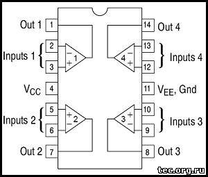
OK. I can see why, now that you said that. I will have to figure out how though as there is no access once they are plugged into the case. No bottom that opens at all.Compare voltages on IC1 pin 14 on both channels.
Tack a test wire to the pins on the solder side.OK. I can see why, now that you said that. I will have to figure out how though as there is no access once they are plugged into the case. No bottom that opens at all.
Put a piece of heat-shrink tubing or electrical tape over the probe tip. Leaving just the very point exposed.Just be extremely careful not to short out adjacent pins with your test probe.
Similar threads
- Replies
- 2
- Views
- 188