

You are using an out of date browser. It may not display this or other websites correctly.
You should upgrade or use an alternative browser.
You should upgrade or use an alternative browser.
Pioneer Sx1010 Repair - Diodes
- Thread starter 70smidfiguy
- Start date

70smidfiguy
Active Member
Thank you, was using other threads.
I think I found the overall issue with my 1010!
Not sure if this is a blown cap or maybe a giant transistor, perhaps a "custom" component?

I think I found the overall issue with my 1010!
Not sure if this is a blown cap or maybe a giant transistor, perhaps a "custom" component?
70smidfiguy
Active Member
Can offset and bias be set while on DBT?
The DC balance can be set on the DBT.
The Idles can be checked for operation/function. Once it's established they are working, you back them off to min voltage and reset them to proper specs on full/line house power.
The DC Balance can be rechecked but should be good.
The Idles can be checked for operation/function. Once it's established they are working, you back them off to min voltage and reset them to proper specs on full/line house power.
The DC Balance can be rechecked but should be good.
70smidfiguy
Active Member
With output tr's in, on dbt was able to set Lch to 0mv (19-gnd) and 50mv (14-16) respectively.
No luck with Rch as really no adjustment available on VR1/VR2 (14-16) currently reading 6.5v so there is a problem on this board.
PS Readings:
15 - 25v
14 - 55v
13 - 35v
11 - -22.5v
10 - -55.5v
9 - -12.5v
8 - 13v
6 - 5.3v
Next step: Should I take the rch board out and review again?
No luck with Rch as really no adjustment available on VR1/VR2 (14-16) currently reading 6.5v so there is a problem on this board.
PS Readings:
15 - 25v
14 - 55v
13 - 35v
11 - -22.5v
10 - -55.5v
9 - -12.5v
8 - 13v
6 - 5.3v
Next step: Should I take the rch board out and review again?
I would revisit the right channel board again, your PS readings look good, check for leg placements on transistors and cap polarity, also if you are pulling these boards out make sure all your re-connects are proper. I would also be careful with that dial needle, those are precious, and you never know what a cat is gonna do. Make sure Q4,5, and 6 are installed correctly..
Make sure you have continuity on all those solders on the back of the board some of them look fishy to me, keep going your getting close.
Make sure you have continuity on all those solders on the back of the board some of them look fishy to me, keep going your getting close.
Last edited:
70smidfiguy
Active Member
kk, thanks for that, will press on.
I should of mentioned the idles are set for 25mv. The manual is incorrect.
good point forgot about that one, starting another 1010 soon
70smidfiguy
Active Member
ok well took the Rch board out again, checked all solders, all looks good, compared with Lch, components are exactly the same. Same ECB arrangement.
19 - gnd = 6.7v (VR1 adjustment has no effect)
14-16 = 3mv (VR2 fully CW and fully CCW has no effect)
sigh!
Left channel set and working for
19 - gnd = 0mv
14-16 = 25mv
DBT dimming. No relay click. NO preamp jumpers installed.
I could try swapping the Lch and rch boards to insure it IS the rch board as apposed to some other issue.
Thoughts?
70smidfiguy
Active Member
Ok will do. What is the impact of preamp jumpers in or out to the overall operation and testing of amp? Meaning, I know what the jacks do, but does it impact measurements?
The jumpers separate the pre amp from the main amps.
If a pre is misbehaving, as in sending unwanted voltage to the main amp. This effects the main, making it impossible to dial in the settings and troubleshoot.
Two separate circuits where the pre can effect the main amp.
If a pre is misbehaving, as in sending unwanted voltage to the main amp. This effects the main, making it impossible to dial in the settings and troubleshoot.
Two separate circuits where the pre can effect the main amp.
70smidfiguy
Active Member
Ok, so finally got Lch and Rch in, relay clicks, light dims on DBT was able to set Lch idles and balance as required, no preamp jumpers in.
On the Rch, was able to set balance to 0mv but even with trimmer set fully CCW could not set idle below 300mv. Adjusting only increased the value.
BTW turns out the Rch major issue was D7 and Q9. Both had been replaced with new components but I guess failed during the transition somewhere along the way.
Thoughts?
70smidfiguy
Active Member
Hi all, firstly thanks to all for your support (Especially Zebulon1) who never gave up on getting this fixed with me!
Finally all is working but i thought I would like to leave a quick note on what I learned in doing this project.
Best practices:
Components replaced: (Almost a restore)
Main Filter Caps
Output transistors and sockets
All parts on PS except resistors and ceramic caps.
All caps and transistors on EQ board.
All caps and transistors on protection board.
All parts on amp boards except resistors and ceramic caps.
All fuse lamps with white LED fuse lamps.
I have a ton of pictures and would be more that happy to share if anyone wants to look at something in detail.
Cheers
Finally all is working but i thought I would like to leave a quick note on what I learned in doing this project.
Best practices:
- Do not remove wire wraps, remove pins from board instead.
- Power supply first, not a lot of components and a relatively low cost to replace them for something that important.Get a solid base first!
- Isolate issues from major first to minor last. (subjective i know) In my case one of my issues was that I had a channel cutting out while adjusting volume. The issue ended up being a bad solder on the bass control pot. After resolving all other larger issues, that was easy to find and repair.
- Make sure your DBT bulb is 150w for this unit.
- Once I learned a few things (The hard way) I virtually repaired and tested everything on this unit while on DBT. Only as the very final step did I switch to direct.
- I replaced the output tr sockets and im glad i did. The old ones were brittle and the pins where pushing out.
Components replaced: (Almost a restore)
Main Filter Caps
Output transistors and sockets
All parts on PS except resistors and ceramic caps.
All caps and transistors on EQ board.
All caps and transistors on protection board.
All parts on amp boards except resistors and ceramic caps.
All fuse lamps with white LED fuse lamps.
I have a ton of pictures and would be more that happy to share if anyone wants to look at something in detail.
Cheers
Bimmerb5
New Member
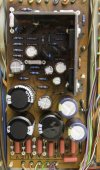
Here are my voltages after complete upgrade:Ok so, I picked up on a couple of things all relating to the PS board:
1) I had used 1845's for the 2SC869's, I have now installed KSC2383's
2) I had used 992's for the 2SA628's, I have now installed KSA1013's
I also replaced the 2 x 33V Zeners (WZ-320's) with 1N5257B's.
Sadly I do not have any 14V Zener's but the WZ-140 did seems to test ok.
So after doing that I reconnected the removed pins from prior instructions and tested again: (on direct, resistors on outputs)
PS 15 = 32.x v
PS 14 = 56.x v
PS 13 = 35.x v
PS 11 = -27.x v
PS 10 = -57.x v
PS 9 = -13.x v
PS 8 = 13.x v
PS 6 = 6.x v
Pin 8 - 12.83V
Pin 9 - 13.16V
Pin 10 - 57.2V
Pin 11 - 23.5V
Pin 13 - 35.1V
Pin 15 - 26.2V
Pin 14 - 57.5V
I replaced the 32V and 14V zener diodes with 33V and 14V.
Attachments

Similar threads
- Replies
- 13
- Views
- 545