Pioneer SA-8500II repair and restoration...

mattsd

Super Member
Here is the thread I promised!

Rundown of what I have found so far:

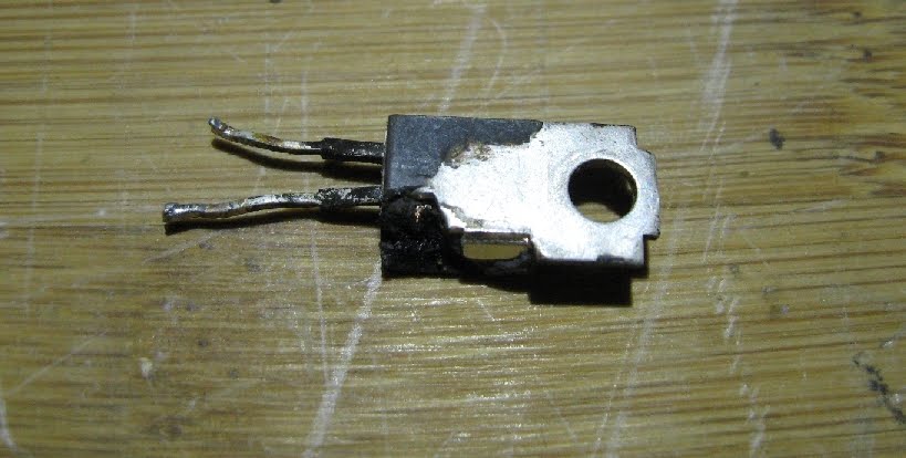
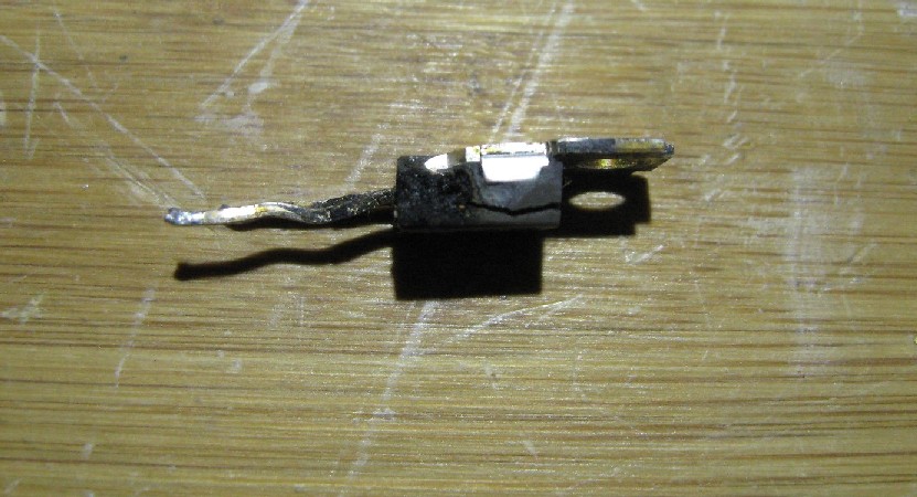
#1: The drivers, 2sb528 and 2sd358 for the right channel are shot, the 2sd358 actually has a piece missing and the board is charred where it was, the other is shorted in all directions.

Some photos of what I mean:

IMG_02023.JPG


IMG_02021.JPG


#2: Two of the right channel outputs are shorted, one shorted in all directions like the b528.

#3: Both R14 and R15, the 150 ohm 1/2 watt resistors next to the drivers are smoked, I'm guessing they looked like glowing filaments from they way they're burnt.

#4: The left channel seems fine, however I have not gone into it thoroughly because of the right channel.

There is also is a oily residue all over everything. I'm wondering what exactly happened with this amp, especially where the residue came from.

So I will need advice on the parts to fix the outputs, and substitute transistors for the drivers, and maybe others. I do have the subs for the outputs, so I just need the solder tabs and hold down bars, plus the screws.

512-FJP1943RTU pnp to-220 bce 250v 17a 80w 30mhz 55-110hfe $1.56
http://www.mouser.com/Search/Product...hVmL11Nw==
512-FJP5200RTU npn to-220 bce 250v 17a 80w 30mhz 55-110hfe $1.08
http://www.mouser.com/Search/Product...M2ys9lQg==

Edit: Did some researching for replacements for the drivers and resistors and found:

2sb528: 512-KSA940 to-220 bce 150v 1.5a 25w 40-140hfe

2sd358: 512-KSC2073TU to-220 bce 150v 1.5a 25w 40-140hfe

R14 and 15: Xicon 293-150-RC

Will those work?
 
Last edited:
Everything but the xicons... I was stupid (about mouser's search)back then.....

BTW, the replacement is straightforward with the a940/c2073 combo, but I ran into trouble with a lower Vbe turnon when I subbed in mje15032,33's (going for POWER!!!) so don't use them as drivers. The idle current will be too high, and will be unable to turn it down FAR ENOUGH...

150 ohms 1/2 watt

660-MF1/2DC1500F 1% $ 0.15

660-MOS1/2CT52R151J 5 % $ 0.15

believe it or not, the hold down bars will probably be the biggest pita of the project, as well as the 30mm screws needed...

www.fastener-express.com ....
 
Last edited:
Believe it or not, the hold down bars will probably be the biggest pita of the project, as well as the 30mm screws needed...

I figured that. The left channel is fine BTW, all the transistors tested very good, but I may replace them anyway, I'm not sure.

BTW, the replacement is straightforward with the a940/c2073 combo, but I ran into trouble with a lower Vbe turn on when I subbed in mje15032,33's (going for POWER!!!) so don't use them as drivers. The idle current will be too high, and will be unable to turn it down FAR ENOUGH...

That seems to be the problem with all the On-Semi's, outputs or drivers. Remember what I had to do with my 525 and 636? I had to put 100 ohm resistors where the bias diodes were to get the current where it should be.

What solder lug did you use, and where did you get it? I cannot seem find that lug. Also, what thread size are the 30mm screws?
 
I figured that. The left channel is fine BTW, all the transistors tested very good, but I may replace them anyway, I'm not sure.

Do one, regroup, but my vote is for symmetry.

That seems to be the problem with all the On-Semi's, outputs or drivers. Remember what I had to do with my 525 and 636? I had to put 100 ohm resistors where the bias diodes were to get the current where it should be.

this is the opposite situation - zero resistance will still yield too much idle current, not good.

What solder lug did you use, and where did you get it? I cannot seem find that lug. Also, what thread size are the 30mm screws?

mouser.com
vendor: keystone electronics hardware...
lug:
534-908 held on by a short 4-40 screw - in a tapped hole in the aluminum...

screw, www.fastener-express.com (2007) :
M3 x .5 x 30mm Pan Phil Machine Screws-S/S Qty 50

Manufacturer Part#: MMSPHPS3030-5H2

(Qty: 1 x $4.30) <<< that's the price I paid in 2007, and it's the same now!!!

The thing is I don't remember if the hold downs were 1/8 (0.125) or 1/4 (0.250) inch thick and whether the 30 mm was almost too long for it, or if the 1/4 made the 30mm necessary.

With the type of socket used, the screw can be much longer, and the excess length will be a danger to causing shorts if it runs into anything behind the socket.

You will have to measure things yourself and determine the correct length for the M3x0.5 x ??? screws which seem to come in 5mm increments.
 
Last edited:
Do one, regroup, but my vote is for symmetry.

I just had that advice from my dad, so I will do that.

The thing is I don't remember if the hold downs were 1/8 (0.125) or 1/4 (0.250) inch thick and whether the 30 mm was almost too long for it, or if the 1/4 made the 30mm necessary.

You said in the thread that they were 1/8 inch thick, 1.100 inches long and 0.500 inches wide, and I can always cut down the screws if there is none that exactly fit.
 
If so, recent experience with 1/4 thick aluminum indicates it is the better choice. 1/8 inch flexes under tension.
 
Is there any other components I should check before I order? Would the STV3H diode have been damaged? I hope not, but...things do happen.

Edit: Whoa! I think I'd better check everything, not just the power amp boards. Q1, a 2sc869 on the switch assembly board, AWS-108, has its entire front half missing! I have ksc2310's and ksc2383's. Will any of those work?
 
Last edited:
test?
Every other transistor on that power amplifier board. every other diode. every other resistor. lifting one (at least two for transistors) lead to isolate the component. even the 0.5 ohm emitter resistors.

we have not addressed the other transistors, no less the failure that caused this disaster - which from the destruction looks like an open bias loop. HAVE you tested the STV-3H? are it's leads intact?

you will be replacing the bias (idle current) pot, so we have a LOT to talk about before you pull the trigger on an order. perhaps a picture...

just off the top of my head:
1n2473's are 512-1n4148 's
10e2 diode is 512-1n4004
100 ohm single turn pot 652-3386H-1-101LF (gotta see a pix of the board)

I haven't decided/calculated which of these two complementary pairs are a better choice for the a912 and c1885's:
512-KSA992FBU (ln)to-92 ecb 120v .05a .5w 100mhz 150-800hfe $0.05 ea
512-KSC1845EBU (ln)to-92 ecb 120v .05a .5w 100mhz 150-800hfe $0.05 ea
or
512-KSA1381es x to-126 ecb 300v .1a 1.2/7w 150mhz 40-320hfe $0.27 ea
512-KSC3503estu to-126 ecb 300v .1a 1.2/7w 150mhz 40-320hfe $0.28 ea
--------- alternative --------
512-KSA1220AYS to-126 ecb 120/a160 1.2a 20w 155mhz 35-320hfe $0.39
512-KSC2690AYS to-126 ecb 120/a160 1.2a 20w 155mhz 35-320hfe $0.40
--------- alternative --------


also
awh-051 c4 22 35 cea 22 50 647-UPW1H220MDD
awh-051 c5 330 6.3 cea 330 6.3 647-UPW0J331MED
awh-051 c13 1 50 ceanl 1 50 647-UKL1H010KDDANA
 
Last edited:
test?
Every other transistor on that power amplifier board. every other diode. every other resistor. lifting one (at least two for transistors) lead to isolate the component. even the 0.5 ohm emitter resistors.

Roger that.

HAVE you tested the STV-3H? are it's leads intact?

I have not tested it yet, however the leads look intact. I don't want to mess with it anymore then I have to because I know how sensitive the leads are. What should the reading on the meter be for this type of diode?

(gotta see a pix of the board)

And so you shall! Here the links to the photos (allows for bigger photos then on here):

http://3.bp.blogspot.com/_3GtE0MBb3LA/TP_SgLpJmII/AAAAAAAAARc/xBA_jC1sMB8/s1600/IMG_02022.JPG
http://3.bp.blogspot.com/_3GtE0MBb3LA/TP_Teei4fcI/AAAAAAAAARk/-Yt5JzPghsw/s1600/IMG_02023.JPG
 
Last edited:
I finally got the measurements, let me know if I'm missing anything and I will edit it in.

R1 330K: 331.3K
R2 2.2K: 2.200K
R3 62k: 62.5K
R4 39K: 39.3K
R5 3.3K: 3.297K
R6 2.7K: 2.713K
R7 2.7K: 2.715K
R8 2.7K: 2.690K
R9 62K: 62.5K
R10 6.8K 1/2W: 6.89K
R11 68: 67.9
R12 160: 162.1
R13 160: 160.1
R14 and 15 are the 150 ohm resistors that are burnt.
R16 0.5 2W: 0.53
R17 0.5 2W: 0.51
R18 0.5 2W: 0.50
R19 0.5 2W: 0.52
R20 4.7: 4.90
R21 4.7: 4.80
R22 2.7K: 2.717K
R23 2.7K: 2.708K
R24 10 2W: 9.5
R25 10 1W: 10.2
R26 2.7K: 2.712K

D1: 563
D2: 560
D3: This is not good, it reads OL in the diode test and in the ohms test it reads 8.24M ohms consistently.
D4: 547

Q1: Black to base 1, red to emitter: 657
Black to base 1, red to collector 1: 647
Black to base 2, red to emitter: 655
Black to base 2, red to collector 2: 646
Every other way is OL

Q2: Red to base, black to emitter: 647
Black to collector, red to base: 638
Every other way is OL

Q3: Red to base, black to emitter: 640
Black to collector, red to base: 627
Every other way is OL

Q4: Black to base, red to emitter: 612
Black to base, red to collector: 647
Every other way is OL
 
Last edited:
Everything but D3 looks good, D3 worries me.

Do you have a few loose diodes laying around?

I would ask you to first measure diode one for it's drop, then two in a string than three in a string to see if your meter is up to reading a STV-3h diode';s drop - or if it has a problem. You could even try 4 diodes in a string just to establish your meter's limits.

As a side note - a weak battery in the meter may affect this test by not having enough voltage to get a full range reading through all the circuitry.

The stv-3h should read in the range of 1.5 to 1.8 volts, with about 1.6v as the target.

after we clear that up, looks like with these parts you are good to go:

the metric screws from fastener express,

the power output transistors (more powerful to-220 batwing replacements)
512-FJP1943OTU pnp to-220 bce 230v 15a 80w 30mhz 80-160hfe $1.21
512-FJP5200OTU npn to-220 bce 230v 15a 80w 30mhz 80-160hfe $0.85

the driver transistors
512-KSA940 pnp to-220 bce 150v 1.5a 25w 4mhz 40-140hfe $0.54
512-KSC2073TU npn to-220 bce 150v 1.5a 25w 4mhz 40-140hfe $0.54

the emitter resistors for the drivers (R14 & R15
660-MF1/2DC1500F 1% $ 0.15
or
660-MOS1/2CT52R151J 5 % $ 0.15

D4 diode 10e2 diode is 512-1n4004 just as a precaution

100 ohm single turn pot 652-3386H-1-101LF (gotta see a pix of the board)(edit - yes it's fine!!)

The rest is superfluous, but could be done:

differential pair amp:
Q2, Q3: 512-KSC1845EBU (ln)to-92 ecb 120v .05a .5w 100mhz 150-800hfe

current source:
Q4: 512-KSA1142OSTU to-126 ecb 180v .1a 1.2/8w 200mhz 100-320hfe $0.28 ea
...... (or) 512-KSA1381es x to-126 ecb 300v .1a 1.2/7w 150mhz 40-320hfe $0.27 ea
although
512-KSA992FBU (ln)to-92 ecb 120v .05a .5w 100mhz 150-800hfe
would work, it could get warm under operation.

D1 1n2473's are 512-1n4148

****************
here's the caps

awh-051 c4 22 35 cea 22 50 647-UPW1H220MDD
awh-051 c5 330 6 cea 330 10 647-UPW1A331MPD
awh-051 c13 1 50 ceanl 1 50 667-ECQ-V1H105JL5 ($0.68) or if out of stock 1 63 667-ECQ-V1J105JM ($0.70)
 
Last edited:
I have a million 1n4004 diodes laying around, so yes, I can do that.

Will be back in a minute with the results!
 
Well, that explains a lot. My meter can only go to 1.000v, so it is possible that it is good, since it was getting a reading on the ohms test. What should I do?

Edit: The test current for the meter is 0.3mA.
 
Last edited:
We'll take it on faith that it's ok, and trust the dim bulb to save us from disaster.
 
Will do. I will order everything then, and I think I'll order enough to do both boards the same, new drivers, diodes etc.

But there is one note, for the outputs I will have to order the RTU's, as the OTU's are out of stock. They are the same as the OTU's except that these are 55-110hfe instead of 80-160hfe. Will those be all right?

Edit: Also: Q1, a 2sc869 on the switch assembly board, AWS-108, has its entire front half missing! Will the 512-KSC2310YBU work? I've looked at the rest of them and it seems to be the only one, but there are two of those darn Sanyo sky blue caps next to it, so I will replace those while at it. I believe the replacement is 667-ECQ-E2224KF.
 
Last edited:
Will do. I will order everything then, and I think I'll order enough to do both boards the same, new drivers, diodes etc.

But there is one note, for the outputs I will have to order the RTU's, as the OTU's are out of stock. They are the same as the OTU's except that these are 55-110hfe instead of 80-160hfe. Will those be all right?

Edit: Also: Q1, a 2sc869 on the switch assembly board, AWS-108, has its entire front half missing! Will the 512-KSC2310YBU work? I've looked at the rest of them and it seems to be the only one, but there are two of those darn Sanyo sky blue caps next to it, so I will replace those while at it. I believe the replacement is 667-ECQ-E2224KF.

those are 250v and if they fit in the space allotted, fine, otherwise
667-ECQ-V1J224JM 63v
667-ECQ-V1H224JL3 50v

2310 is fine. better than fine.


otu to rtu difference is ok.
 
Update...

I got the parts for the board, the outputs and the screws, 4-40's and the M3's, so I'm just waiting on the aluminum. I have replaced on the board:

C4
C5
C13
D1: 1n4148
D2: 1n4148
D4: 1n4004
Q2 and Q3: ksc1845
Q4: ksa1381
Q5: ksc2073
Q6: ksa940
R15 and R16

Some photos of the repaired board:

http://3.bp.blogspot.com/_3GtE0MBb3LA/TQvgskxDLfI/AAAAAAAAASE/a9sFPU0gw_g/s1600/IMG_0151.JPG
http://4.bp.blogspot.com/_3GtE0MBb3LA/TQvgsZqpGnI/AAAAAAAAAR8/or_zvgjGKpM/s1600/IMG_0150.JPG
http://1.bp.blogspot.com/_3GtE0MBb3LA/TQvgs3PMczI/AAAAAAAAASM/YvJQAIAnFw0/s1600/IMG_0152.JPG
 
hey!! what about:

100 ohm single turn pot 652-3386H-1-101LF (gotta see a pix of the board)(edit - yes it's fine!!)

or we could be right back in the same boat if the pot is either damaged or intermittent.

When I first read this I was beating myself up for not including the idle current adjust pot (seeing the old one in place), then I went and checked to confirm that I had overlooked it in the re-compiled parts list... I hadn't....
 
Darn it, I completely forgot to add that to my order after you had revised the list. :tears: This the second time I've done this. :grumpy:

Looks like another Mouser order were I'll have to eat the shipping, unless Digi-key has it, I do know that they still ship first class and it's a whole lot cheaper.
 
Back
Top Bottom