Sansui QRX 999

bourvil

Member
Hello all!

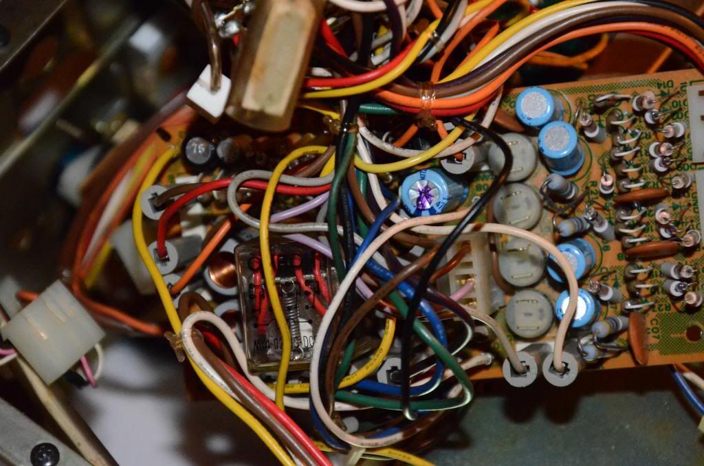
As I must be really addicted to Sansui I could not resist to get this beast in nice condition but with typical problems including drifted values of fusistors, no signal on several modes and muffled sound with tendency to disappear on one or both channels overall.
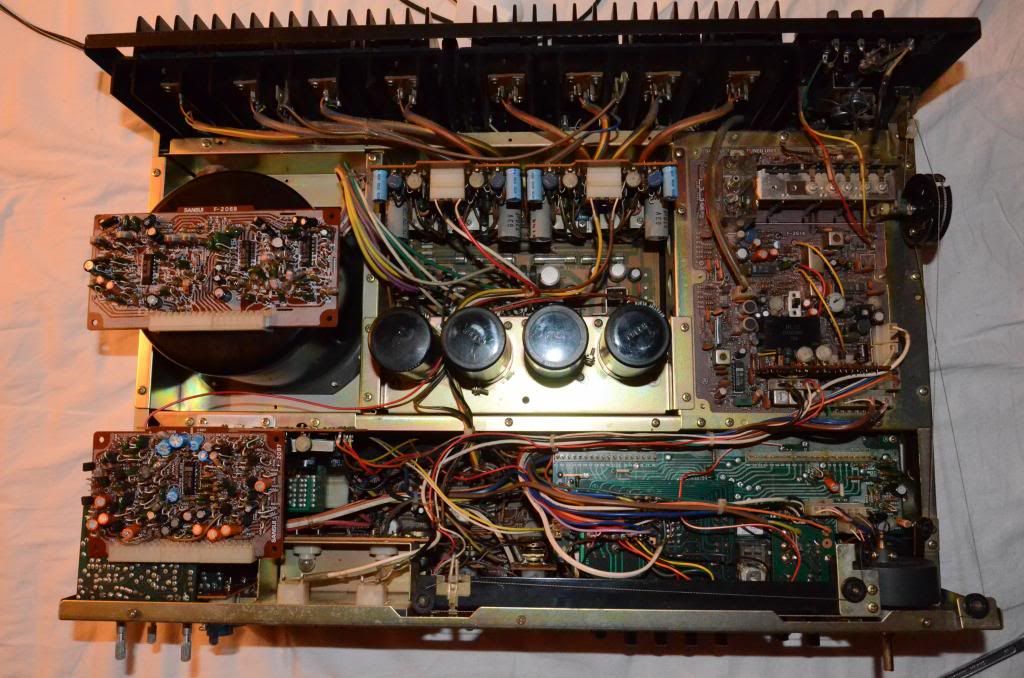
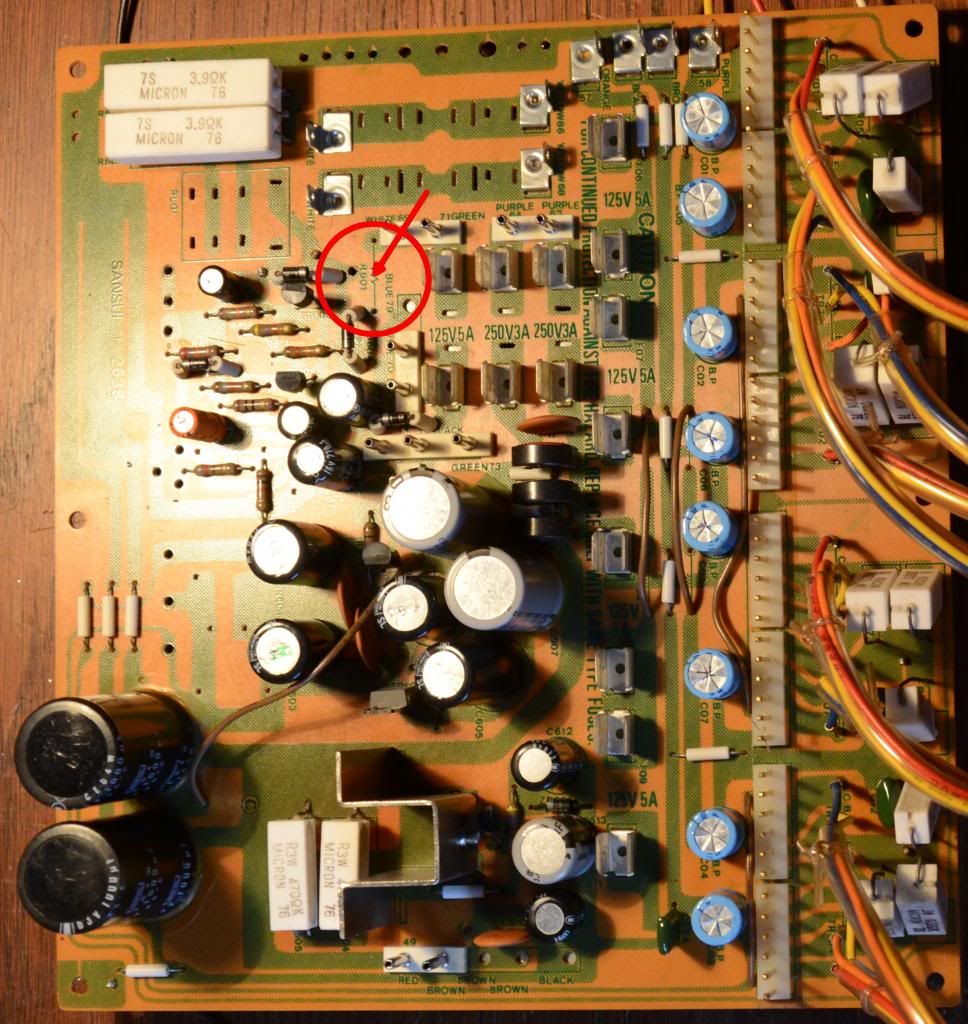
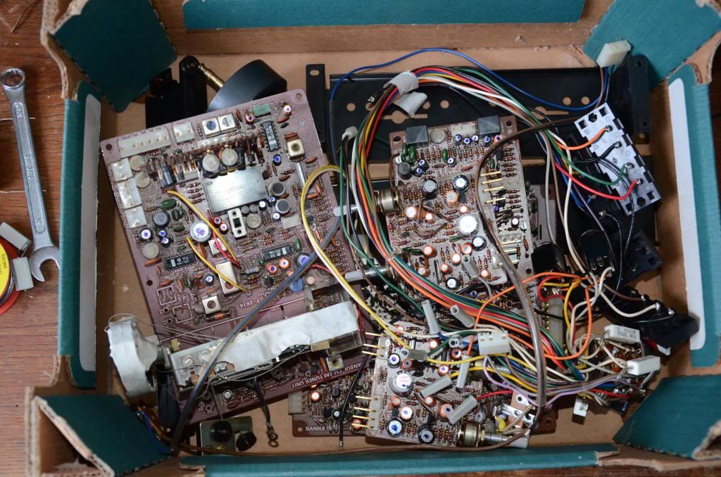
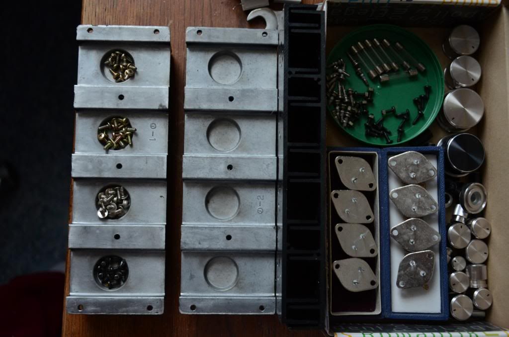
I plan to do full restoration including recap, replacing fusibles and all other components out of specs or those proven to be faulty (VD1212 etc.)
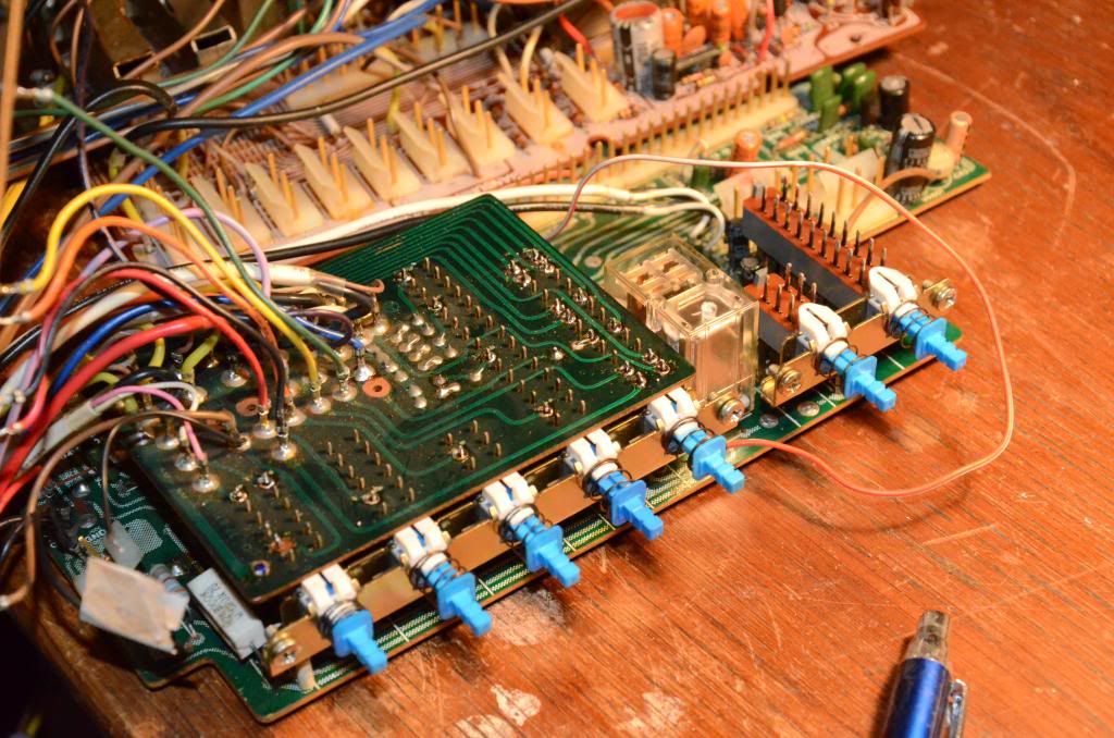
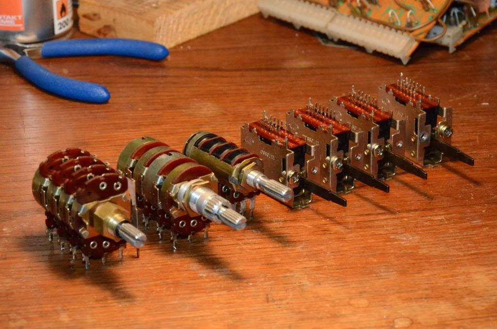
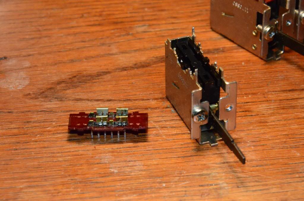
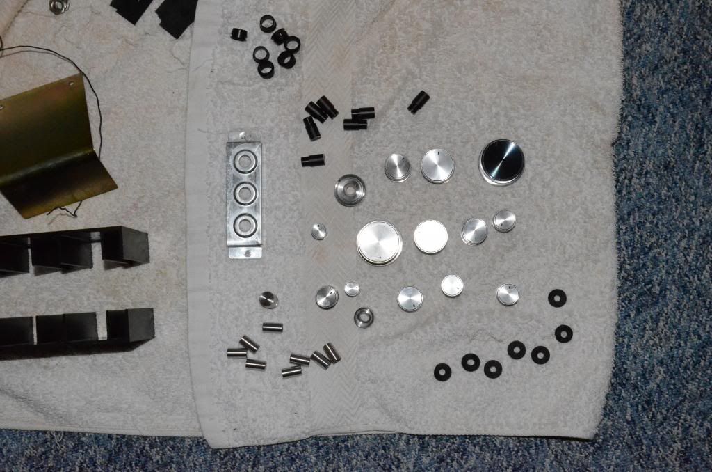
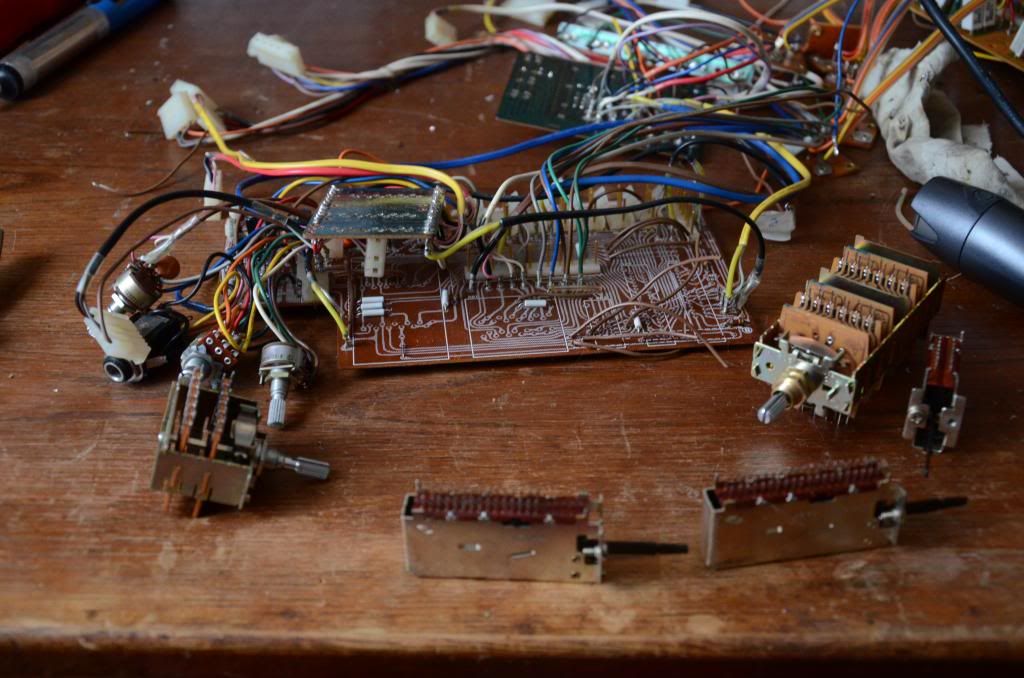
I also plan to clean all unit inside and outside including disassembling and cleaning of switches, pots and relays.
As guru of restoration Kale I would like to share experience (and photos of course) with all of you during this challenging restoration.

Finally I must say big thanks to Trnsfmr for his invaluable QRXrestore web and many others who regularly contributes to this great site.:tresbon:

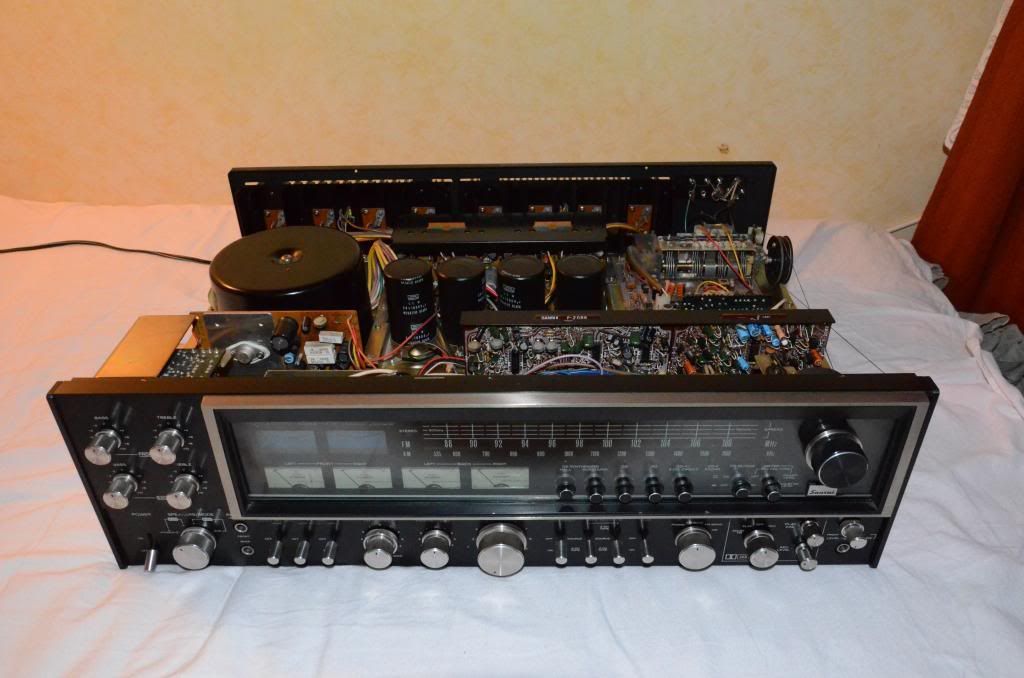
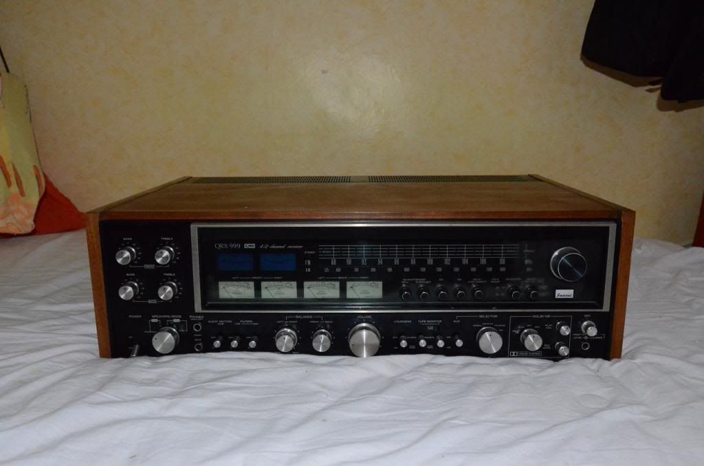
So for now, how it all started: SOme days ago I got this small pckage into my music den. it was HUGE and heavy as anvil.
DSC_2201_zps878ccd08.jpg


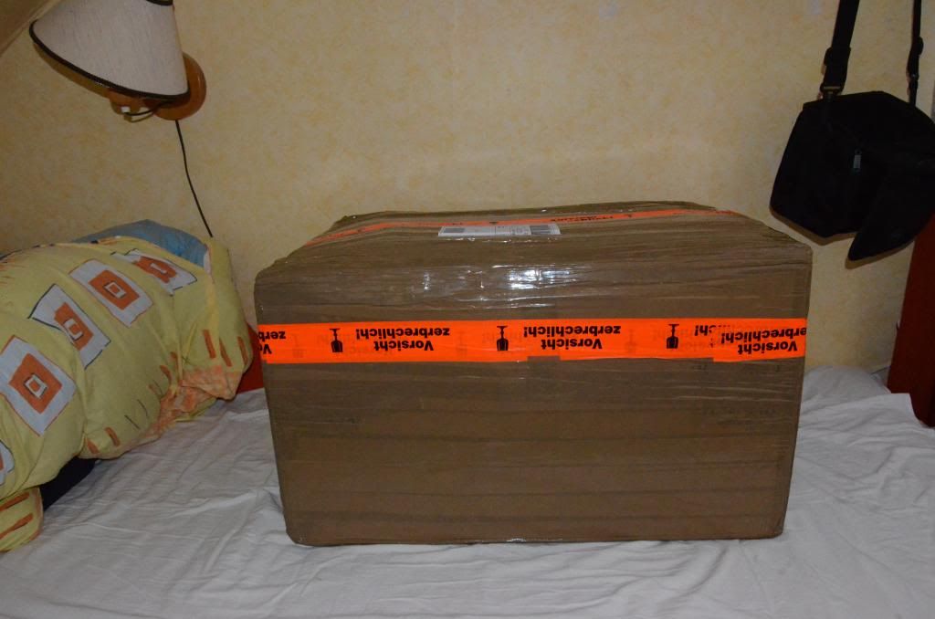
It took some time to get the treasure from very well packed box and this was the result:
DSC_2203_zpsdcac24c9.jpg


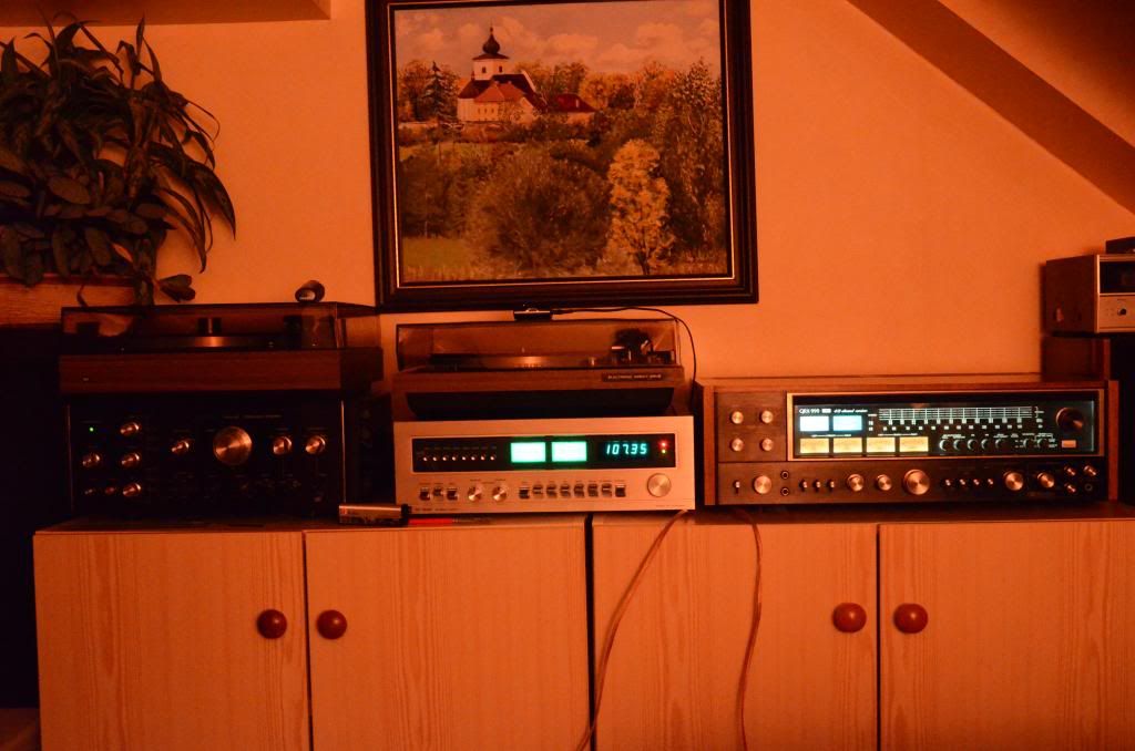
I set it temporarilly on the place in my system to examine how the unit works and where are the problems. Almost all lights are working and as the place arround the bulbs is only light "smoked" it seems that this unit has low running hours what is great:banana:. Although, majority of switches must be dirty as only source I got relatively clean was dolbyized radio. All other sources were muffled and after some time one or both channels came out which was crowned with loud click from speakers when I turned the unit off.
DSC_2205_zpsebec0462.jpg

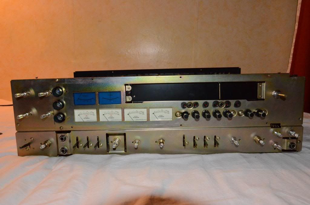
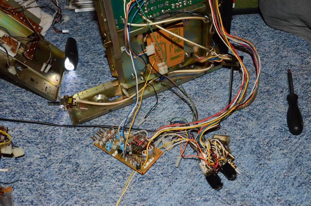
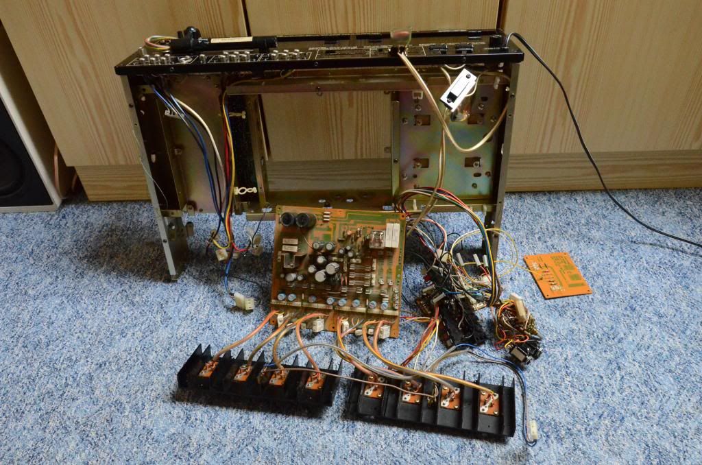
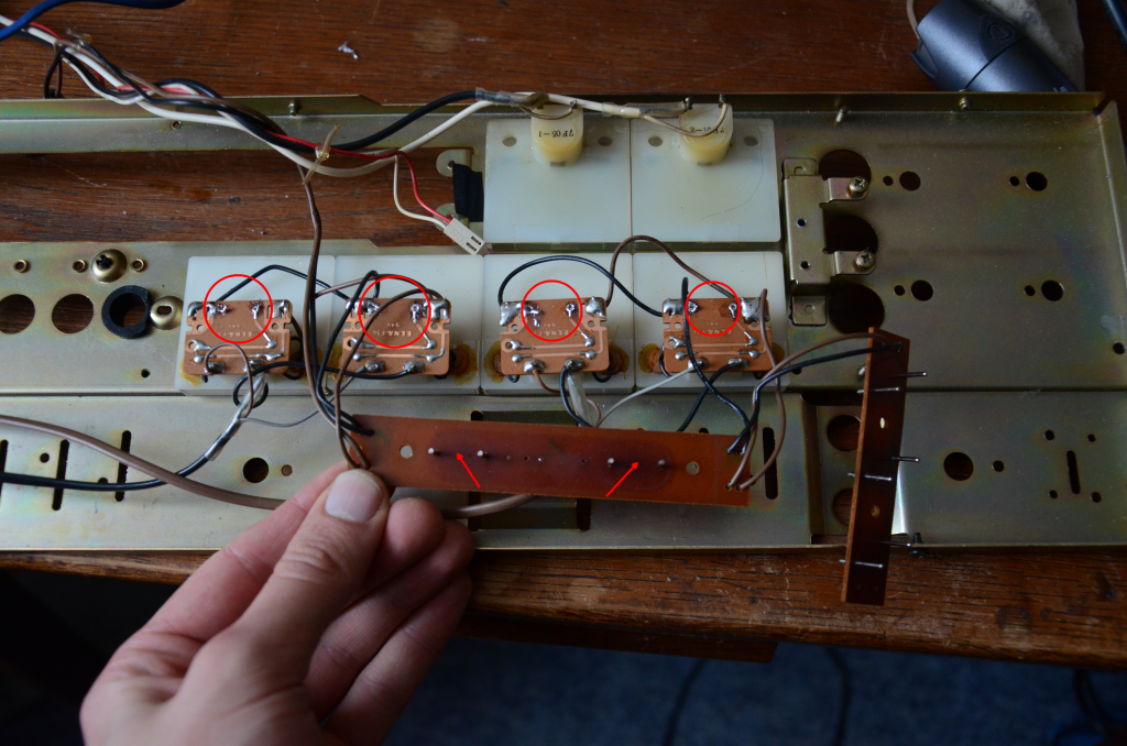
Next step is to open the unit and examine the condition of internals so stay tuned!:music:
 
The QRX-999 is probably the best quad receiver ever made, but it's also among the most complicated. Documenting everything is a good idea. It will give you good reference as you put it back together.

We're all watching. :)

- Pete
 
Do you know what you will replace as far as caps? I too have one and have no sound at all. . .

You need to find the fault(s) first before you go replacing any caps. (unless they are proven faulty).

Welcome to AK by the way :thmbsp:..... best start your own thread - having 2 QRX-999's in the same thread will be very confusing - the guys & gals will be able help you much better this way :thmbsp:
 
Last edited:
It's always best to fix any faults before recapping. That way if you won't have competing problems to diagnose if you get a cap in backwards. Besides, the caps are rarely the cause of no audio output.

- Pete
 
Pretty piece! Definitely something you don't see every day. I've got a qrx-9001 collecting dust here...one of these days i'll get to it.
 
Yes, this one is definitely nice preserved bud need a lot of care and maintenance too.

So for electrolytics I am going to use these types of caps:
Nichicon KL for low leakage ones (the orange ones)
Nichicon KW for those in audio path and not the KL types
And finally Nichicon VZ for those in power supply and near the hot parts
The main filtration caps would be Nippon Chemi-con KMH 10000 uF With the same dimensions as originals are.

So, let's continue.

After removing cover I realised that there is almost no dirt inside except the oily film covering all the upwards surfaces. And there is also a lot of dust in this thick and sticky film. All was in normal condition, no burnt or fried components, even no brownish spots on PWBs. As unit lacks serial number sticker I do not know when it was manufactured and only clues I have are that the drivers are in diode bias adjusting version and there are no thermal fuses on the top of heatsinks and there are much smaller yellow posistors attached directly on heatsinks between PNP and NPN pairs of power transistors.
DSC_2252_zpsaab57126.jpg

This unit is tremendously complex and I count 23 boards at all connected witch huge quantity of interconnects. It is good idea to use massive connectors and Sansui used them a lot so thanks to it disassembling is relatively easy. Also it is good that the contacts are gold plated so they are not affected with corrosion which is dreadful on silver plated contacts.

First thing was to unmount the front face and this is the result:
DSC_2259_zps73f03912.jpg

Next to disassembe aeasy to remove boards without soldering:
DSC_2267_zps7a3e049e.jpg

And on and on it ended into mess like this:
DSC_2304_zps0688768f.jpg

This rotary switch is propably the most complex and most chaotic part of the whole unit. Thankfully many wires are easily deconnectable from protection board. But cleaning of this switch will be a battle...
After digging inside and parting unit to more pieces and handling situation like this:
DSC_2328_zps1f35f7e4.jpg

I finally managed to get the starting point of restoration of all boards and internals. It is the famous double sided board 2634 which will be refurbished first:
DSC_2336_zpscf903cc0.jpg

This board is like sandwich and it consist of 3 pieces of board. before You can properly resolder the through pins you have to remove the smaller two board soldered to upper pins of push switches.
There I realized that maybe someone was working on this unit in past as there are some bypasses for damaged paths on the plates. First one was on the smallest one where two contact were completely lost and one was repaired with thin black wire:
DSC_2332_zps1eee19b2.jpg

There is also other bypass from red-white wire on the board itself. It seems it is bypassing the bad pass-throughs and was soldered during some repairs. You can see this bypass on the bare board:
DSC_2341_zps8a687708.jpg

There is a need to unsolder the relay and switches and rework all the pass-througs which would be a quite demanding job as many of you noticed yourself. You can se that many pass througs are in bad condition and many of them are full of rosin and not with solder so no surprise they are no more working.... And there is also some thick oil or vaseline (the dirty black spots between the longest switches) but I do not know its purpose...

There was also mistake which look it was made in factory and it is missing solder on one lead of capacitor on this board:
miss_zps0e9db25e.png


Next time I will show this completed board and we can turn to another one...
 
Do you know what you will replace as far as caps? I too have one and have no sound at all. . .

Refurb if this unit is quite complex and demanding job and as I never done one I can only judge from others experience. I am going to use this list in this order:

*Clean all the switches and pots and inspect and clean relay contacts or replace them
*Fix and resolder the pass through solder joints on the double sided pc board
*Replace the fusable resistors with normal 1/2 W metal film resistors.
*Replace the VD1212 and shorted or corroded diodes
*Measure transistors and repalce faulty ones
*Replace all the electrolytic caps
*Add the 25V regulator

And after this I would do these things:
*Remove the 3 blend resistors on the quad processing boards
*Do the “Holy Grail” quad alignment
*Realign the tuner
*Set the amplifier offset and bias to factory spec

Is there anything I missed?
 
Wow !

This thread is going to be a lulu ! (I mean this in a good way :) ) - nice work so far bourvil :thmbsp:

:lurk:
 
Last edited:
Seems the Big quads are coming out of the woodwork. I just picked up a 999 myself. If you need any reference help when assembling It let me know. I can clearly see its one of Sansui's more complex units. Taking a tone of pics truly helps when your putting it back together. Later Fever
 
Sorry guys for not being here for some time. I would like to have twice the time to do things :tears:

Wow !

This thread is going to be a lulu ! (I mean this in a good way ) - nice work so far bourvil

No problem Hyperion, I am glad you are enjoying this thread. I will try to do the best to document all the story of restoration:music:

And thanks johny-fever for offer. I am taking a ton of pictures (actually the number is alround 400 :thmbsp:) but no one knows and reassembling the unit will be uneasy

So where we all ended last time?

Yes the sweet double sided board. I removed the switches, both relays and got it all cleaned and defluxed. And all the holes are now bad solder free and prepared to repin:
DSC_2353_zps1007770c.jpg


Repining is really quite a hard job. It took me almost 3 hours to repair all the connections. After every junction I measured it with DMM to prove its perfect function.

Next step was to unsolder the diodes and capacitors which will be replaced. Although diodes are functional I will replace them as 10D1 diodes used in this receiver are known to get fault very easily. The good replacement id 1N4004 or whatever from this series. And lastly almost all capacitors had lowered capacity and orange ones were completely dried (even they are sealed with epoxy) This is barebone double side board ready to join new components: :banana:
DSC_2357_zps4cdda449.jpg

Next board to repair is the volume and switches one. First task is to unsolder all the switches. On next picture there is not visible but in reality the whole board is the dirtiest one thanks to leaking oil from pots and switches.
DSC_2389_zps41923aee.jpg

Here is the separated army of operating instruments :D
DSC_2400_zps2c4b110e.jpg

And obligatory picture of internals of one switch full of mixture of viscous former oil and dirt and corrosion:
DSC_2404_zps308b36c0.jpg


Meanwhile in other place, the dismantling of unit continues:
DSC_2358_zps039244e2.jpg

Controls are cleaned:
DSC_2397_zpsdf805647.jpg


And last picture for now (or two). As I said in former post on my unit there is unfortunately missing serial number. But inside I found sticker on power transformer with some number and the date. As it is year 1980 in which this receiver was no more produced I think that it is date of servicing of the unit. There was some changes on mentioned double sided board and I think that it come from this era when unit was in service:
DSC_2378_zps472bb52d.jpg

And last picture for now (I promise:D). On the bottom of power transformer I found this:
DSC_2379_zpsdd2bc247.jpg

There is number 77 and some symbol and I think that this could be the year of manufacture. So my unit was probably manufactured in year 1977.

What do you think? Is this hypothesis right?

Thanks for your support, encouraging, enjoy this story and stay tuned!
 
Hello again.

I have not been there for some time but this is not a proof that I gave up the renovation.. But I have other things to do and proper work need its time...

So last time I ended with totally dismantled unit and now I have almost 100 separate parts including PCBs, switches, relays, covers, knobs and many other hardware relating parts.

Last time I had almost refurbished double sided board. It is complete now except new capacitors and new drop resistor for relay which is not 24V as before but 12V and as a bonus it is now easily removable thanks to socket.
Here it is almost done with separated relay. The brown wire interconnect were moved to other (bottom) side of the PCB
DSC_2450_zpsc0a80c55.jpg


Other board which is almost done now is the switch one. All switches cleaned and works like new. There is second place I used same relay in socket just like on the double sided board. Work to do is to replace all caps and same dropping resistor just like upper in this post.
DSC_2462_zpsb02b0a5c.jpg


Next board to get processed is the function switch board. This one is probably most complex witch numerous connectors, wire interconnects and with huge number of wires attached directly into board itself. There are two "sandwitch" selectors with three lever ones and as you probably guess they were all very dirty and oxidized too. Also there were many interconnects from brown wire which were obsoletly long and contributed to make even bigger mess around this board. So to classic maintenance work including cleaning all the switches and board itself I am going to add shortening all these interconnects to make layout clearer.
Here is the board with removed switches and about to start reconnect shorted brown wires which you can see on the right side.
DSC_2451_zps4697d9f1.jpg

On this board (on the right side behind the soldered wires) is row of same connectors which promise that reconnecting would be a hard work. But these are labeled with letters and on appropriate connectors there is small sticker with the same letter - hey - this is very useful!

In time between the work on the boards I replaced AC plug with wire and completely cleaned the whole back plate including main power switch. There was BIG problem. Small metal levers inside the switch were completely burn on one side and one was damaged so badly that when the switch was in "ON" position there was hardly any contact. But fortunately this switch has two position and both have contacts so it only needed to flip the whole back of switch upside down to use previously unused contacts. But to the future it would be good idea to replace whole switch with new.
DSC_2457_zpse5d8e227.jpg


And next to back side is.....front one. There is not much to do. All bulbs are OK and I do not plan to rework the lighting to LED one... But it is a good idea to inspect every bulb and clean contacts. On the small plates attached to power meters there were soldered fusible (!) resistors to drop voltage for lights. Thankfully they did not drifted in its value or even shortened so I think that is time to replace them witch regular ones. They all were 22 omh each - 4 for power meters and one for bulb in tuning indicator. On other plate you can see the brown from the heat but it is only cosmetic and this plate would function long years without issue.
DSC_2454as_zps308713ce.png


Concerning fusibles I found one more on power supply board which I believe is last. It is only 1 ohm and it acts like fuse. You can find it here:
DSC_2460as_zps3a2127ad.jpg


This is all for this time. I know I still have a lot work to do. Last think I made up is definitive list of replacement capacitors. I count 248 of them and I have them in table with defined type and rated voltage. I found several lists but none of them was like my so I do not know if it is caused by difference between each manufacture version. There is also list of fusibles and other parts which would be replaced. I wait until I will have complete list of all parts because I plan to order them from Mouser as there in Czech republic is no reliable source of quality parts. And because shipping fees are quite high I wait to make one big superorder (and maybe I will reach the free postage)

LIST you can get there: SANSUI QRX 999 (9001) PART LIST

I am not afraid I will not have something to do because there is box full of components waiting to get refurbished:
DSC_2473_zps12521f49.jpg

I am starting to have room full of parts, boxes and so on:
DSC_2471_zps85924765.jpg


In the end THIS RESTORATION will be challenge! much more complicated than the LEGO Technics but in the end much more delightful... or did you see LEGO 4CH amp??? I like Lego and other building sets but on the other side I like the vintage too and the most I like the music.

So in the end I do not have much possibilities, I must like Sansui and I do. I love it! Thanks Sansui for all this fun I am having with restoring which is promising musical nirvana for me!

PS. but if we are in LEGO mood This is not bat either...
3688642084_f476de9c61.jpg

but surely Sansui is better toy.

End...fur now at least

Thanks for your attention, feel free to comment or ask and next time here again (hope it will be shorter delay) with next part of story of magnificent MONSTER...
 
Although I am a big fan of Sansui,don't know why these quad receivers have never been interested me like big G's, so rarely look at the thread about them.
But I see you've done your homework and studied many posts on this forum, and therefore this restoration will certainly be successful for sure :yes:

For now,you are progressing very well and your work is well documented too.
I'll follow this thread with pleasure...thank you :thmbsp:
 
Beautiful work. Watching the progress is like watching audio porn. You just can't take your eyes off it. There is still a lot of work to do so we should be entertained for some time to come.

- Pete
 
I just checked the serial number database and the 8 QRX-999s on file were manufactured between December 1976 and November 1977. There are many more QRX-9001s on file. They were manufactured between October '76 and March 1978.

- Pete

-
 
Thanks for all your comments. I hope this will be good story to tell and I hope it will end in happy end too. I think I will not complete this restoration in less than 2 month so there will be a lot of story to tell in future.

I just checked the serial number database and the 8 QRX-999s on file were manufactured between December 1976 and November 1977. There are many more QRX-9001s on file. They were manufactured between October '76 and March 1978.

- Pete

-
Well if it is true that 77 on transformer means year of manufacture, then we all are watching on porn with 36 years old main actress :D
 
Thanks for all your comments. I hope this will be good story to tell and I hope it will end in happy end too. I think I will not complete this restoration in less than 2 month so there will be a lot of story to tell in future.


Well if it is true that 77 on transformer means year of manufacture, then we all are watching on porn with 36 years old main actress :D

She's 36, but still a raving beauty with a strong voice.:music:
 
Well, where we ended up so many day ago? Yes, shame on me for letting you wait so long... But we are continuing from now until happy end....:thmbsp:

There were more reasons why I got this delay. First was that I was counting and double checking the list of parts to be ordered. This got enormous time (with addition of other parts for other audio equipment I am willing to restore too) so I placed order no earlier than on the end of June. And yes, second reason was that weather was much more pleasing to be doing something outside as summer definetly came.

So I ended up with all parts disassempled, cleaned and where i had more boards from one type (driver, tone amps) I unsoldered all parts to be replaced from one of them to think up about rearranging the interconnects to make better layout and to inspect all semiconductors as well (even I was going to replace many of them). So here you have some comparisons:

Here are all capacitors removed, glue cleaned and all deadly fusistors eliminated as well.

These are fusistors from one driver board - quite high number to make some troubles when they decide to drift its value (In my unit there was almost no drift but you never know and there is nothing more easy than replace these and have clear mind forever :yes:)

Board without heatsinks with all transistors except big driver transistors replaced. All interconnects waiting to be shortened and attached back to board in more aesthetic way.

All transistor which were put down from the board, none of them failed but smallest one had bad corrosion on legs and their hFe gains were not equal on left and right side. New were carefully paired within maximal diference of 3.

And finally this is new VD1212 diode!

And last picture concerning the drivers, the duo of NEW one and OLD one - last thing I would do is to reduce gain but not now - maybe in the future.:scratch2:

For now all, next time we will be interested in tone amps and other parts

Bye for now:banana:
 
Back
Top Bottom