A 400C Transformation

dcgillespie

Fisher SA-100 Clone
Subscriber
It's all AKer Ivan100000's fault. He sent me his ailing 400CX-2 preamp for repairs, and I promptly fell in love with the thing when I was finished. He had the unmitigated nerve to actually want it back, so that was that. I started looking for examples for sale, which were few and far between, and when they did come up, the price was simply absurd. They are a wonderful preamp to be sure, but their price -- like ALL such outrageously priced equipment -- is primarily a function of their rarity, rather than the unobtanium performance/features they deliver over other more common pieces of similar equipment.

So, I started mulling about for a nice 400C. This was Fisher's very first stereo effort of any kind, and represents the origin for some of the standardized design efforts that followed through to numerous succeeding models of various types (preamps, integrated amps, receivers, console tuner/preamps, etc.), some of which followed through to the very last vacuum tube units Fisher produced.

Topology wise, it is a slightly simplified version of the 80-C and 90-C premium mono preamp offerings that preceded it, but the 400C represents the point where standardized component values began for many of the future small signal audio circuits of all things Fisher. Specifically, with only minor exceptions, the component values used in the 400C phono preamp followed through to every single piece of Fisher stereo equipment that followed it that had a magnetic phono input, and the active tone control network component values followed directly on through to the 400CX and 400 CX-2 preamplifiers and X-202, X202B, and EL34 based X-1000 premium integrated amplifier offerings. This includes the typically wonderful tracking dual tap 100K volume control that Fisher used in these tone control circuits. With a vacuum tube rectifier and DC heater power supply, the 400C then contains the most important basic building blocks of its more famous later versions. That meant that if I could just find a decent one, then I could go through it and rather easily upgrade it to provide the wonderful performance I had measured and heard in Ivan's unit earlier.

But since the 400C is an older unit, it is often in worse physical shape when available. A current look on the auction site will prove that. And, it is the later version of the 400C I wanted that has the individual tone controls for each channel and dropped the somewhat goofy crossover feature, so that narrows the field down even further. Therefore, while going this route is certainly easier than going for a real 400CX-2, it is still challenging to say the least.

Enter my good friend and fellow AKer Audiodon, who just happened to have a 400C of the type I was looking for. So typical of Don, it was a good looking unit, and was the version I was looking for. But there was a catch. This particular 400C was in many, MANY parts an pieces, carefully stored in a box from a previous gutting/rebuild effort that went awry some years earlier when the low level selector switch was found to be broken. So there it sat, with copious notes, schematics, parts and pieces and a broken low level selector switch. In one of the previous equipment ventures Don and I have had, he had sent me that switch, which I was able to successfully repair and send back to him. But by that time, with all his current work and the requests for work he gets, the steam was gone behind the 400C project for him, helped in no small degree by the Preamp Output Jacks his X-1000 and X-101C integrated amplifiers now offer. So there it sat for yet another year, until my quest for a Fisher preamp began in earnest.

When I received it from Don, it was packed to the hilt as he so typically does, complete with all of his notes, a nice set of tubes, and various containers of removed parts, mechanical parts, and parts yet to be installed. It was going to be a formidable project to say the least, but I was undaunted.

It is always interesting to pick up someone else's unfinished project that stopped midway through the effort, and now has, er....some age on it. Nothing of the project is fresh for recall, and the available Sam's schematic was already known to not only not match the version I had, but have numerous inaccuracies for the version it did represent. And, I'd never worked on, used, or heard a 400C either to know of any of it quirks as originally offered -- just the promise of the sound I'd heard from Ivan's 400CX-2 that I wanted to achieve in this 400C.

After addressing a number of initial basic issues, developing a neat game plan for going forward, and nearly reassembling/rebuilding it from scratch for a common build style from beginning to end, it reached the point that some basic testing could begin. While the basic building blocks were good, and the plan could ultimately return the performance I wanted, it turns out that being Fisher's very first stereo offering, it did in fact come with a number of quirks and design/build "features" that to my mind left it lacking against the 400CX-2 performance I witnessed earlier. Most notably was various amounts and timber of hum depending on the various control settings and connections used.

To be honest, I'm very picky about any extra hum or noise over base circuit operation. I HATE it, and will pursue it to the ends of the earth to eradicate it. This unit had plenty of it by my standard, which always spoils the listening experience for me just knowing that it's there, even if I can't hear it while the music is playing. Judging from some other threads and folks I've talked to, it's apparently not uncommon with these units. To my mind, that's just not how a Fisher should operate. Cutting to the chase, I have prevailed -- but the fix is rather intricate and involved. However, my 400C now emits nothing but a soft hiss under any condition of use, and delivers all the sound and performance I had heard from Ivans CX-2.

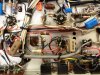
The pics show just how well this unit turned out. Don had already done some serious cleaning on it, but still various panels he had yet to get to told the tale of just how filthy this unit originally was, coming rather obviously out of a heavy smoker's home. The other pics show the significant changes made to eliminate the hum from this unit. The effort was quite effective. Some of them are obvious, some, not so much so. Maybe some of you other 400C owners can spot them. In any event, they'll be detailed in upcoming posts.

Stay tuned....

Dave
 

Attachments

  • SAM_0839.jpg
    SAM_0839.jpg
    70.5 KB · Views: 672
  • SAM_0840.jpg
    SAM_0840.jpg
    86.2 KB · Views: 571
  • SAM_0834.jpg
    SAM_0834.jpg
    122.7 KB · Views: 659
  • SAM_0835.jpg
    SAM_0835.jpg
    125.5 KB · Views: 648
  • SAM_0836.jpg
    SAM_0836.jpg
    107.4 KB · Views: 632
Last edited:
Every time I come across a thread like this, especially Dave's, I end up saying, "Now what do I have to sell now to get one of these??????"

:lurk::lurk::lurk::)
 
Yes, I ran out of steam on this one and moved on. Since I have pretty much the same preamp in the front half of my X-1000, and since Dave was looking for something I had, it looks like this has turned into a win-win situation for both of us.

It's lovely to see it together again and functioning. Though it had its share of nicotine on every surface due to how convection works, it certainly didn't have a smoky late-night sound.
I see quite a few changes under the chassis.
 
To be honest, I'm very picky about any extra hum or noise over base circuit operation. I HATE it, and will pursue it to the ends of the earth to eradicate it. This unit had plenty of it by my standard, which always spoils the listening experience for me just knowing that it's there, even if I can't hear it while the music is playing. Judging from some other threads and folks I've talked to, it's apparently not uncommon with these units. To my mind, that's just not how a Fisher should operate.

First, excellent workmanship there Dave.

As for the hum, I speak from the SS point of view, but the entire ground layout is an engineering project equal to the rest of the unit and is sometimes not understood even by those that do understand it. My tube experience is WAY in the past and probably never included anything really "good" but it seems that a lot of ground connections were simply ... well, .... connected to ground. Have you considered lifting and isolating some of those ground circuits and connecting only at a star point? For example, on a SS preamp, even power bypass caps should have a separate ground that should be returned to the main ground upstream from the star (signal) ground.
 
Looks good. I'll be interested in hearing what was done with it to make it better than new. I always learn something from Dave's endeavors.
 
You're getting very close to one important part of the fix Fred. And you are surely correct about good ground engineering, and the problems that hap-hazard grounding can produce. Somehow I don't think your tube experience is very much lost at all!

Dave
 
i'm signed up looking forward to your ground fix and other needs. my 400c is dead quiet in all but go figure the eq position. your work from the pictures is clean and detailed. post on i'm all ears.
 
Hi Stl -- The problem is how you define "dead quiet", and I don't mean that to challenge your comment, either. Mine was dead quiet as well -- if the volume was turned full down. And turning it up to play music, you would not hear it except in all but the quietest passages. However, if you advance the volume, that's when the hum was very apparent, particularly out of channel A. And, the character of the hum, and the hum level in each channel would change significantly depending on how the output selector was set -- similar to yours, although my output selector doesn't have the EQ settings.

As a basic point for comparison, I am using 101 db efficient speakers (Cornwalls), with each channel powered by a 35 watt power amplifier having a sensitivity of 1.5 volts to produce that power output. The 400C has a line level gain of 8.7 with the balance and tone controls centered. This means that 35 watts will be produced from each channel with a line level input of just .17 vac, which is quite sensitive, coupled with the sensitive speakers on top of that.

Under this condition, with the 400C's volume control advanced to maximum with the Aux 1 input open (no connection) but selected, there is nothing but hiss from the speakers in both channels. Advancing the bass control in this scenario adds body to the hiss, but no hum. Before the work to reduce it, the hum was readily apparent from my listening position between passages with flat tone controls.

You may think this is extreme, but any signal that the preamplifier is adding of it's own accord must be changing the character is the music, no matter how subtly -- or at the very least annoying me be because it's there!

Should be able to get more posted on the project in the morning.

Dave
 
Hum Problems -- The Issues and Resolve of Them

When completed with a lead dress and wire routing in keeping with the original Fisher build, my unit displayed:

1. Quiet operation when the volume was minimized.

2. Elevated hum as the volume was advanced (notably 120 Hz hum).

3. Changing hum levels as the output control was rotated through its various settings.

After the usual suspects of filter caps, tubes, ground terminal mounting integrity, and power switch cap cover were eliminated from the equation, a more earnest effort began to determine the sources of the hum.

In this unit, there is a perfect storm of issues leading to elevated hum levels, particularly in Channel A. These include:

A. The location of Channel A circuits relative to the power transformer/power supply location,

B. Power supply layout, and

C. Use of a very high impedance design at the input to the line stage that will pick up the slightest tune from any nearby source.

With these factors established, it was then determined that the hum was originating from four different sources, those being:

A. Fisher lead dress,

B. Chassis ground points in Channel A,

C. Power supply component location, and

D. Panel lamp wiring.

These all provided ample noise for the extremely high impedance input circuits of the line amp in Channel A to pick up and amplify as hum. Since this input circuit appears before the volume control, it explains why the hum is most prevalent when the volume control is elevated. Each of these issues require their own fix for resolve, but first, a quick comment on the input circuit of the 400C's line stage is in order.

The 400C represents the last time this type of input stage design was used in Fisher amplifiers of any kind -- almost surely because of the high sensitivity they have to noise, versus the ever reducing size of the jam packed stereo offerings. It is a carry over from a basic design that dates back to at least the 50-C designs of the early 50s.

This design is signified by the use of a large tail resistor (R28 and R61 on the Sam's schematic) that allows for current feedback to be developed within the input stage. This type of feedback increases response, reduces distortion, and increases the output impedance of the stage, but also greatly increases ("bootstraps") the input impedance well beyond the amount that the simple 2.2 meg grid resistor for this stage would suggest. In this case, it is raised by a factor of 5, so that the input impedance of this stage is effectively 11 megohms. Such a high input impedance is on the order of that used with high sensitivity vacuum tube volt meters (VTVMs) used back in the day, making the stage very susceptible to picking up any hum noise available to it. By comparison, all designs after the 400C use simple voltage feedback provided by a resistor from the output of the first line stage, back to its input grid, with a series input grid resistor between the source and this grid. This provides the advantages of improving response and reducing distortion, without raising the input impedance of the stage. For all practical purposes, the input impedance of such a design is not significantly higher than the value of the input resistor itself. Common values that Fisher used in these later designs for the input resistor is anywhere from 390K to 560K. At some 20 times lower input impedance then, it makes such stages far less susceptible to noise pickup, and much more generous in terms of design layout allowances relative to potential noise issues. It's no wonder that Fisher changed to a less problematic design. However, since it is part of the 400C's overall topology, I decided to leave it in place, and deal with the sources that this eager beaver circuit design was picking up. They include:

FISHER LEAD DRESS: This was generally quite good with one exception. Fisher routed the shielded output lead from V3A that represents the Recording Output jack signal for Channel A (and which ultimately then runs on to the volume control) along the rear apron amongst a long run of HV and filament AC wiring from the power transformer to the rectifier tube socket. This is poor practice, as even though the lead is shielded, the intensity of radiated EMF from the power transformer wiring it is running along with can penetrate and produce hum in channel A from this source. It is the only audio lead Fisher routed in this manner in this unit. Additionally, while the HV leads from the PT are twisted, the heater wiring in my unit to the rectifier tube was not from the original Fisher build, which further aggravates the issue.

It is quite easy to disconnect this audio lead from the end most T-strip it connects to near V3, remove it from the back apron area, and reroute the lead to run down the center line of the chassis away from the power supply AC wiring and then reconnect it to its terminals. The lead is plenty long enough to make this change, and is shown rerouted in the pics provided. In my build, this is a white w/black stripe shielded lead. Finally, the heater wiring to the rectifier tube should be properly twisted to minimize noise from this source.

COMPONENT LOCATION: In any low voltage DC power supply, ripple currents can be high. With the filter cap for this supply located at some distance from the bridge rectifier serving it, the long leads act as a transmitting antenna, broadcasting 120 Hz hum for the Channel A line input stage to pick up, which it does. If the bridge is replaced with a silicon unit, the ripple currents are even greater, making matters even worse. The solution to this problem is to use heavy duty shielded cable between the bridge and filter cap, routing it along the back side of the chassis away from the Channel A circuits, to eliminate the antenna effect. Additionally to restore normal circuit operation and minimize transformer heating, a 2.5 ohm resistor (made up of four 10 ohm 1 watt resistors in parallel) should be placed between the + output of the bridge, and the first filter cap. This not only prevents the increase in peak currents when the bridge is replaced with silicon, but also causes the audio tube heaters to operate from the proper voltage in spite of today's higher line voltages. It also allows for an additional change made to minimize the 400C's ability to carry its own tune.

PANEL LAMP WIRING: Sensitive circuits and AC wiring do not mix well for low noise operation. In this case the power lamp is located right in the thick of the tone control wiring, particularly for Channel A, and snakes up to the selector switch array to control the indicator lamps. Granted, the switched lead is at ground level, but with the sensitivities this design has, it is still questionable practice.

The easy solution here is to change out all the lamps for equivalent 28 volt lamps (#8384), and power them from the 25 volt DC source for the audio tube heaters. The added load is small, and accounted for with the bridge dropping resistor mentioned previously. Problem solved.

CHASSIS GROUND POINTS: Fisher used two completely separate ground systems in the 400C -- one for each channel. Each system consists of four separate ground points, one for each stage of the design. In low current preamp designs, such practice generally works pretty well -- as long as the grounds are not near the power transformer area. That area is often contaminated with noise from the transformer, and can easily make its way into the audio circuits via the various ground loops that are caused by the multiple ground point design. Guess where the circuits of Channel A reside? While the two channels individually could be made to be relative quiet, the problem comes in when the ground systems of the two channels are then connected together by way of external equipment that is connected that employs a common ground between its input or output connections -- or, the output switch interconnects the channels by way of its various configurations offered. That then produced all manner of changes in hum level due to different output switch settings, or associated connections used.

While the resolve for this issue could take on many forms, the easiest option was to carefully drill out the rivets mounting the ground terminals of the Channel A T-strips to the chassis, and then remount them using nylon hardware to insulate the ground terminals from the chassis. Then, four new leads were installed to connect the like ground terminals of Channel A to the like ground terminal in Channel B -- whose ground terminals remain firmly connected to the chassis. Since they are located some distance from the power transformer, they are "clean" grounds, which now serve the identical circuits in both channels. The various hum levels from various switch and connection configurations instantly disappeared.

OVERALL: All of these efforts then work to produce a properly quiet 400C, and can all be seen in the original pics provided. A well designed preamp should contribute basically nothing more than the hiss produced from the amplification process. While my unit was originally a long way that goal, that is now the case with my 400C. Your unit and installation may not show the concerns mine did, but there is little doubt that the issues raised are common to all 400C units.

Finally, due to the sensitivities of this design, the use of over sized components in this unit is just asking for problems, due to the antenna affect mentioned (both from a transmit and receive perspective). It can also play havoc with response issues due to the potential for interaction between the larger components. Just be aware of this fact as you proceed with any of your own potential rebuild efforts.

Next time, I'll post the other modifications made to enhance response, control action, and other changes to produce that glorious CX sound, along with some simple changes to help protect the tubes as well.

Dave
 
Fine Detective Work

Again the importance of wire locations, component locations and lead dress such as shielding.
Plus as Dave 'rooted out'- even the dial light wiring in this case. Change to 24 volt DC. An elegant, yet simple solution.
 
Outstanding work Dave! Chasing down hum or noise certainly is no treat. It's easy to assume this old stuff may just be a bit noisy. You knew though that it doesn't have to be that way by design. So glad to hear you were successful. I've been lucky with my 400C, very little noise issues. Just recently though I have been flirting with another amplifier other than my 30A's. It's a modern stereo tube amp and now the system produces a bit of buzzing from mostly Channel A. I thought the amp just didn't like the 3 meter interconnect I use, though the 30A's had no problem. After reading your post. I wonder now if it has something to do with the grounding between both channels in the stereo amp as opposed to using two mono's. The 400C is a great piece, so glad you were able to get your hands on one. Looking forward to the rest of the story, thanks.
 
HiFi -- Thanks for the kind words. It may in fact very well be that because you were running separate power amps, that portion of the 400C's ground circuits remained separated, which reduced your noise issues. It's not surprising however that the buzz that you are now getting is primarily from Channel A when using an amplifier with common input grounds.......

We each have our own acceptance level for extraneous noise, on top of the variations in our systems as a whole, let alone those from one 400C to the next. Therefore, one person's noise problem may be someone else's step up from something far worse before.

I can say however that now I truly do not miss not having a 400 CX-2. Yeah, they're newer looking, have more features, and the indicator array is more useful on the CX(2) versions, but it's the sound I was after, and I am completely satisfied that this 400C is now the equal of a CX(2) version, if not maybe better. All the important building blocks are there, but the signal path is simpler. And, this unit is a very fine example of the breed from an appearance standpoint, so it really was as Don said, a win-win situation all the way around.

Dave
 
Dave,
Your threads have opened my eyes to the following:
1. Factory design and wiring is not always perfect.
2. Input impedance and sensitivity in stages can be optimized - and sometimes should be.
3. Grounding and eliminating hum is as much art as science.
4. Keep working at solutions by process of elimination

Unfortunately, the resolution methods for these vexing issues is for the expert, doesn't follow a checklist, and is learned through trial and error.

I had been thinking that building an amp (with no pre) from scratch would teach me a lot, but even finding good general practice comments like wrap AC filaments and route them against the outside of the chassis are difficult to come by.

Ultimately, it's experience and process of elimination that will win the day.
 
Last edited:
Dave you've given me a good place to start and by you description of the hum/noise sounds are just like the left channel on my 400c. Its slight and you can hear it with your ears starting a couple of feet out. But like you I don't like any unwanted noise/hum.

Your detailed list of fixes is outstanding. Will give it a go today and hear where it takes me.

The thought of taking my 400c to 400cx status is like a dream come true.
Mike
 

Attachments

  • 2013-03-17_15-39-50_758-1.jpg
    2013-03-17_15-39-50_758-1.jpg
    96.9 KB · Views: 153
Thanks Mike -- yeah, hum I can hear a couple of feet out drives me bonkers. I'm confident that the fixes will help you cut it down to size. Thanks for following along, and let us know how it turns out!

Dave
 
Back
Top Bottom