

You are using an out of date browser. It may not display this or other websites correctly.
You should upgrade or use an alternative browser.
You should upgrade or use an alternative browser.
A 400C Transformation
- Thread starter dcgillespie
- Start date
Audio Modifications
While the building blocks that comprise the C and CX versions of this preamp are the same, the stuffing in between those blocks is different -- not to a huge degree, but different none the less. I'll address the phono preamp differences first, as their differences are rather simple, with the remainder of the information pertaining to the line stages. But first, an overview of the basic differences will help.
Besides the rectifier tube, the C uses 6 audio tubes to the CX's 9. The differences here lies in the fluff used to create the additional features of the CX over the more basic C version. Both units use virtually the same phono preamp circuit, with the C then passing the line level signal through 4 stages, while the CX passes them through 5 before appearing at the main output jacks. The 3 extra tubes in the CX support the rather unique Stereo Dimension control, the blended Center and Remote Control outputs, and cathode follower output stages for the main output jacks of the CX unit. Again, this is all fluff, as between the main building blocks of these two units, all the necessary amplification is available to achieve the necessary gain with wide response, and a low output impedance. Of note however, the line stages of the C version provide a measured gain of 8.7, while those of the CX version provide a measured gain of 10.9. This difference is ultimately of little significance and unchanged with the modifications suggested. Also, BOTH of these units invert absolute polarity, which is important to know if this matter concerns you.
PHONO PREAMPS --
Within the phono preamps, the only changes necessary to bring them up to CX status are to:
1. Add 100K shunt resistors at the RIAA 2 input jacks, and in the earliest versions of the C, add them to the RIAA 1 input jacks as well, if not already present. This will cause both of these inputs to reflect a more standard 50K input impedance for magnetic cartridge applications.
2. Within the preamp module, the 100K resistor currently connected to pin# 2 of the preamp tubes should be moved to the other side of the 10K resistor also connected to this terminal. This move allows the 10K resistor to still effectively act as a grid stopper resistor, but eliminates the voltage divider effect these two resistors created in the original design. By preventing a near 10% signal loss then, this move improves the S/N ratio of the unit by producing 10% more output from the phono section, without using any additional amplification to achieve it.
3. Ensure that the interstage coupling cap is effectively a value of .01 uF -- either by way of a .01 uF cap, or two .005 uF caps connected in parallel like my unit had. Yes, the CX used a .022 uF in this position, but it also used a 4.7 meg following stage grid return resistor, where as the C uses a 10 meg resistor in that position. Therefore, the time constant is the same when the C uses only a .01 uF cap for inter-stage coupling.
The phono preamp output stage coupling cap in the C's phono section is also only a .022 uF versus the CX's .047 uF. But again, that's because the preamps in the CX are each driving TWO 250K output level controls, where as in the C, they are only driving one. So again, the time constant is the same in the C with the smaller .022 uF cap in this position.
It is because the CX's phono preamps are driving two level controls that the output stage grid return resistor was lowered, and the two coupling cap values were increased. In spite of these changes however, the response of the phono circuits between the C and CX/2 versions of this preamp is identical.
LINE AMP STAGES --
The line amp stages of the 400C were designed at time when phono was king, and FM was up and coming. It was also designed to be the central figure of THE home entertainment system under all conditions of use. This produced two results:
1. The LF response was appropriate for the available mediums of the day, while midrange response was slightly enhanced, and
2. The volume and loudness functions were very accommodating for low volume listening conditions after little ones went to bed.
Taking the volume/loudness functions first, the design of the loudness circuit in the 400C makes for greatly reduced volume control action in the first half of rotation, throwing most of the control's action beyond the 1:00 setting. This does accommodate low level listening very nicely, but today, it can also throw more normal listening levels outside the control's range where the loudness function operates for those who wish to use it. After all, our hobby is such that when this equipment is on today, it's usually because we are actively LISTENING to it! Additionally, the C's loudness circuits do not provide HF enhancement to go along with the two step LF enhancement provided by its loudness circuit, resulting in a somewhat muddy result from the use of this control.
Fisher realized this heavy skew towards low level listening left a weak impression against the increasingly dynamic music and mediums of the 60's, and so made a change to the loudness circuit that was introduced into all of the premium product lines following the 400C, since all of those units used the same volume/tone control design of this unit. The result is that the volume control action was enhanced in the first half of the control's rotation, the loudness function was changed to a simpler one step circuit, and HF compensation was added into the loudness action as well. It works beautifully. Since the volume control is the same between the C and CX units, all that is required is to change the loudness control components associated with it to those used in the CX/2 models. In my implementation of this change, the first loudness switch position provides both the low and high frequency boost of the CX model, while the second position provides just the LF boost of the CX model, without the HF boost added. That makes this setting similar to the characteristics of the original C model.
Even if you do not use the loudness function regularly, this is still a very worthwhile modification to make, as the increased volume control action below 12:00 is a welcomed change.
Regarding the response issues, today, digital mediums have extended deep bass information, going well below that which was available at the time the C was being produced. That, plus the fact that electrically larger components of the day that would accommodate an improved LF response could not physically fit into the space provided, so the LF response ended up being reduced by today's standards. Also, with the response accuracy of today's mediums, there is no reason to artificially boost any portion of the audio bandwidth when set for flat response. These issues are easily corrected by simple component swap outs as follows. Using the Sam's schematic for the left channel then:
1. C22 should be changed to .005 uF. This flattens the response of the stage, eliminating the slight mid frequency boost.
2. C23 should be changed to 1 uF (non-electrolytic).
3. C4 should be changed to a 47 uF.
4. C28 should be shorted out and eliminated.
5. C5 should be changed to 100 uF.
6. C31 should be changed to 1 uF (non-electrolytic).
Make the appropriate changes in Channel B as well. Additionally, I found that C50 in my unit was more accurate at 10 pF, rather than with the 8 pF supplied, although such a change will not be audible. It's mate C29 was found to be accurate as is.
These changes will allow the 400C to have all the LF response of the CX/2 versions, and the same flat response characteristic throughout the audio bandwidth as well.
The results of these changes collectively make for a very much improved 400C. The volume control is responsive and well positioned now for power amplifiers of typical sensitivity. The full bass register is there with authority, without any false emphasis throughout the entire audio spectrum. The loudness function works superbly, and together with the changes made to eliminate hum, it is now dead quiet now as well -- even with the improved LF response it now sports.
Fisher must have thought these were worthwhile goals as well, as they were all improvements added into their CX/2 models as well. In all my efforts to modify/improve/enhance Fisher equipment, I never try to turn them into something they are not, or cause them to make a spectacle of themselves. Fisher equipment is typically known to sit quietly ready, rising to any challenge given it, and accomplishing that task with unequaled poise, character, and class. The modified 400C accomplishes all these things qiote ably now. I would like to think that Avery would approve.
In the last post, I'll detail some worthwhile power supply changes to make the unit a little more forgiving to its tubes, and take care of a few small socially unacceptable behavioral issues. I'll also post a few scope shots of the final response achieved.
Dave
fred soop
Super Member
.....
You may think this is extreme, but any signal that the preamplifier is adding of it's own accord must be changing the character is the music, no matter how subtly -- or at the very least annoying me be because it's there!
.....
Thanks, Dave.
Your comment drove me to work on the 600-T residual hum problem and change the ground on the control preamp bypass capacitors.
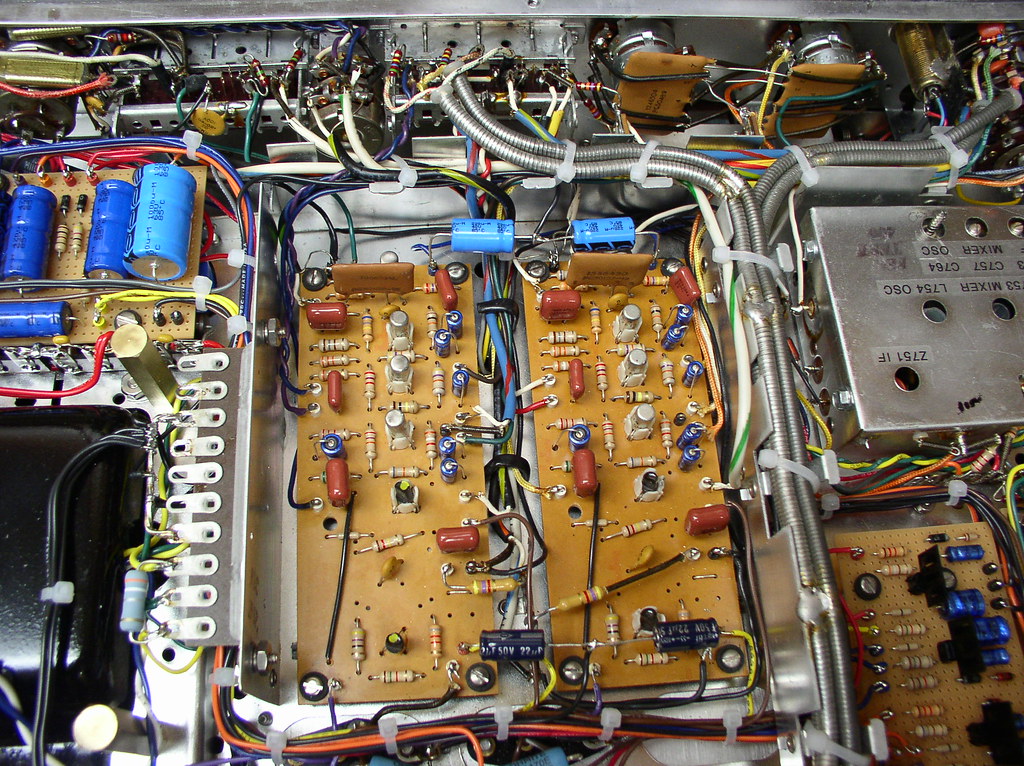
Each of these was connected between B+ (actually B- since it is a negative supply for PNP transistors) and the ground terminal directly below the joint between the caps on the circuit board. The left cap was connected to ground on its board out of the photo. The circuit board ground is a signal ground. I also increased the value of these capacitors as music could be heard with headphones connected to the B- terminal.
1442

The other 2 bypass capacitors similarly connected. I don't really like the "flying" joints but the ground wires immediately go into secured bundles so these are not going to move at all. The correct solution would require redesign of the circuit boards to isolate the grounds. The ground wires from all 4 caps go to the ground bus next to the transformer, the pair of wires nearest the bottom, almost out of sight just under the 5th lug.
1443
The hum is GONE except another slight residual in the multiplex. That may be magnetic coupling from the power transformer to one or more of the coils.
fred soop
Super Member
Notes on Loudness Compensation .....
Of course, the purpose is to provide tone compensation so that the perceived balance at low volume is similar to that at high volume. The mistake made by many manufacturers is to attempt to correct for the uneven response of the human ear rather than DIFFERENCES in response at different levels.
Open a new browser window and bring up the graph at:
http://en.wikipedia.org/wiki/Fletcher–Munson_curves#mediaviewer/File:Lindos4.svg
Let's assume that we want to properly correct for response at 60 dB below maximum, using the ISO 226:2003 curves (red lines). The same process would be used if you wanted to use the original Fletcher-Munson curves (blue lines) with slightly different results.
At 1000 Hz, the 40 phon curve is 60 dB below the 100 phon curve, by definition.
Now look at the spread between the curves at 5000 Hz. They are still 60 dB apart. At 10 kHz, they are at 114 phons and 54 phons, but still 60 dB apart. No compensation is needed for high frequencies. So far, Harman Kardon seems to be one of the very few that got this correct and not even on all of their equipment.
On the low end, look at 400 Hz. The 100 phon curve is still at 100 dB SPL but the 40 phon curve is at 44 dB SPL, or a 56 dB spread rather than 60 dB. 60 dB - 56 dB = 4 dB of boost required.
At 100 Hz, the 100 phon curve is at 108 dB SPL and the 40 phon curve is at 63 dB SPL. 108 dB - 63 dB = 45 dB. 60 dB - 45 dB = 15 dB of boost required. Most circuits that I've seen set this boost at around 7 - 10 dB.
At 20 Hz, the required boost is a whopping 34 dB. This would be difficult to achieve without some complex circuitry, or supplementing the loudness compensation with advancing the bass control.
Additionally, these required boosts are only for one signal level. The required boost changes with overall volume level.
Lots of inspiration here, considering that I have about 1 2/3 400Cs boxed up in the basement. One is the early version with the "locked" tone pots, the other is the late version with the dual-concentric tone pots. The faceplate I have is for the early version. What is the crossover function found in the early models, and what replaced it on the later ones?
I have yet to decide if I should rebuild the later model with the early faceplate, or keep it all original with some performance tweaks as described here. I only have one tone switch assembly (which had a wafer that had to be glued back together), so I can only rebuild one.
I have yet to decide if I should rebuild the later model with the early faceplate, or keep it all original with some performance tweaks as described here. I only have one tone switch assembly (which had a wafer that had to be glued back together), so I can only rebuild one.
Fred -- Sorry to get you aggravated at your own hum issue, but glad you found it!
None of these "corrections" are meant to cast any negative light on Fisher at all. Their products as produced still represent some of the best products ever made. But still, manufacturers do make errors that often simple tweaks can resolve as you just proved. And so it is with the 400C as well.
Your comments on the loudness issue are dead on. Personally, I believe that the competition between manufacturers to produce the most "accurate" loudness compensation effect ended up being resolved by the consumer rather than the engineers. Whether it was correct or not, consumers overwhelmingly preferred the traditional approach as exemplified by that used on the CX/2 series of preamps, which provided a set amount of low and high frequency boost up to a certain point of rotation on the volume control. Before that time, loudness circuits were often quite complex, which most often served more to confuse the consumer rather than help them.
Eico was famous for using both a fully variable loudness control and a volume control on many of their mono amplifiers and preamplifiers, which most folks never did understand how to use correctly. On their stereo integrated offerings, the loudness switch function worked so adversely compared to those like on the CX/2 that most folks -- even today -- think it is broken, or that the schematic is in error. Nope. It was just their take on how to do it "properly". Virtually all folks today modify the loudness circuit on their Eico stereo integrated units with a well known "fix" for the "problem" they have. Sometimes, the engineers just need to give it up, and give the consumer what they want! In this case, Fisher wised up, and did just that.
Sam -- the Crossover A and B functions was an effort to take mono signals applied to either Channel A or B and break it into a crossed-over signal, that sent low frequency signals to the channel A speaker, and high frequency signals to the Channel B speaker. The switch settings simply chose which channel the signal was being taken from. With either settings, LF information was always sent to the Channel A speaker, and HF information sent to the channel B speaker.
This feature didn't find a lot of favor with the consumer, so it was replaced with two new settings for "Channel A" and "Channel B", wherein only the selected channel's speaker produced sound, and only from that channel's input. In this way, it served as a balance check function, as it is quite easy to tell if one speaker is playing at a different level than the other with this feature.
Finally, it is interesting to note that for all the various settings on the Output Selector Switch in the 400C, there is no way to operate this preamp in a completely mono mode, where both channel's inputs are blended to produce a mono sound in both channel's outputs. It's not a particularly missed feature for me, but in correcting this "flaw", Fisher went so far as to install mono settings for phono and FM operation right on the main selector switch in ALL of their future products after it.
The version with the locked tone controls seems to have come from console installations, where individual tone controls would not really be needed, since the speakers would be guaranteed to be identical. For their stand alone versions however, early stereo installations often did not have the same speakers used in both channels, so those versions used the dual-concentric pots to allow adjustment of each channel individually.
Dave
stltrains
Active Member
Dave the changes you mention in the loudness section do they apply in any switch position. Or just effect when the loudness sw is in use.
I use the loudness sw on my 400c as the power sw so I would have to do more mods to bring the loudness sw back to service. But if it will increase volume levels in the off position I will do it.
Mike
I use the loudness sw on my 400c as the power sw so I would have to do more mods to bring the loudness sw back to service. But if it will increase volume levels in the off position I will do it.
Mike
Hi Mike -- Yes, the changes to the loudness circuit make the volume control more responsive whether the loudness feature is engaged or not. But this is as compared to the original design. If you currently removed the entire loudness circuit to free up the loudness switch for AC power duty, or to use a non-standard volume control that doesn't have any loudness tap connections available, then reinstalling ANY loudness circuit with the original volume control or otherwise will reduce volume control response from having no loudness circuit installed at all.
On the other hand, if you did retain the original volume control and loudness components in the circuit, but merely wired the components as "off" to free up the switch, then changing the components to the later values will in fact improve control response.
If I may however, using the unshielded loudness switch for AC power duty is really asking for hum problems in this unit, as is using unshielded, loosely twisted AC power wiring for its connections as well. This would be particularly true for later versions where the cross-over feature was eliminated, as in those versions (like mine), the output mode switch is inserted into the circuit at the input of the first line amplifier stage where the sensitivity of this section is the highest -- as opposed to the earlier versions with the cross-over feature, that insert this switch at the output of the last stage, where sensitivity is the lowest.
If you no longer have the original AC switch, its shield, and the AC power wiring shielding sleeve -- or at least suitable replacements for all of these things -- then I would suggest removing all of the AC power wiring running up to the control panel area, and simply wire the unit as permanently "on" at the rear receptacle area, using an external switching arrangement for controlling AC power.
Dave
Last edited:
Sam -- the Crossover A and B functions was an effort to take mono signals applied to either Channel A or B and break it into a crossed-over signal, that sent low frequency signals to the channel A speaker, and high frequency signals to the Channel B speaker. The switch settings simply chose which channel the signal was being taken from. With either settings, LF information was always sent to the Channel A speaker, and HF information sent to the channel B speaker.
This feature didn't find a lot of favor with the consumer, so it was replaced with two new settings for "Channel A" and "Channel B", wherein only the selected channel's speaker produced sound, and only from that channel's input. In this way, it served as a balance check function, as it is quite easy to tell if one speaker is playing at a different level than the other with this feature.
Dave
The Stromberg-Carlson ASR-433 actually has both of those features in stock form. Crossover basically turns the thing into a bi-amp rig, but also on the switch is A only, B only A+B, reverse, and stereo. There is also a balance check that turns the neon power indicator into a relaxation oscillator so you can adjust the individual channel levels to center the output. I have removed all of that in an effort to clean up the signal path, and it made nice improvements IMO.
Miscellaneous
In this last installment, I'll outline some simple things that can be done to make it a little easier on some of the tubes, and address some minor behavioral issues as well.
POWER SUPPLY
1. The first section of the 12AT7 tubes (V3A and V6A) have the signal provided to them via direct coupling from the previous stage. This places about 150 vdc on the grids of these tubes, which more importantly, causes the cathodes to operate at about 153 vdc. At issue here is the fact that with the cathodes of these tubes operating at such a high potential, and the heaters inside the cathodes representing only a 12-13 volt potential on the low side of their heater connection, this places a difference of more than 140 volts between the heater and cathodes of these tubes worst case, or at least 128 volts best case -- and this for a tube that is rated to have no more than 90 volts peak appear between its heater and cathode. In short, the design of the 400C stresses the heater/cathode insulation of these tubes to the max. For tubes that already require good selection to find low noise examples, subjecting them to this stress is potential trouble just waiting to happen.
The solution is to apply a heater bias to the heater supply to elevate the heater system appropriately above ground, to reduce the heater/cathode difference so that it resides within specifications for the tube -- without unduly stressing the other tubes in the process.
Normally, providing a DC bias to the heater supply is done in an effort to reduce noise. But in this case, it serves no purpose towards that end because the heaters are already being powered from a DC source. In this case, the bias is simply applied to reduce stress within the 12AT7 tubes.
To perform this procedure, it requires that the original filter can cap for the heater supply cannot be used, since its negative side was firmly grounded to the chassis by way of its mounting tabs. However, since most examples today have replaced this cap with either discrete caps, or discrete caps stuffed inside the original can (as Don had already done with my unit), it means that problem likely no longer exists, so it only requires that the ground connection for this supply system be lifted from ground, so that the bias can then be applied.
The bias itself is developed by a simple three component network, connected between the 320 volt power supply point, and ground. It consists of:
A. A 270K 1 watt resistor connected between this source, and a convenient tie point. In my execution of the modification, I used an unused terminal on the rectifier tube for this new tie point.
B. From this new tie point, a 68K resistor (1/4 watt is fine) is connected to ground, as is a 10 uF 100 volt electrolytic cap, with its positive side connected to the tie point.
C. Finally, a 10K resistor (1/4 watt) is then also connected between the new tie point, and the negative side of the (now ground lifted) DC heater supply. The rectifier tube socket can donate an unused terminal to help facilitate this connection if need be.
The pics provided in the first post clearly show this network and its installation in and around the rectifier tube socket in my unit.
This network develops about 65 vdc, and applies it to the low side of the DC heater supply system. This reduces the voltage difference between the heater/cathode elements in this section of the 12AT7 tubes to just within the 90 volt specification limit worst case, without causing the heater cathode voltage to be unduly stressed in the other section of this tube, and the 12AX7s in the unit, that operate with their cathodes at more traditional levels. It's one of those modifications that simply gives peace of mind.
This modification also works nicely with the panel lamp modification as well when the lamps are converted to 28 volt lamps that operate from the DC heater supply. That's because no portion of these lamp sockets are grounded by was of their mounting, allowing their sockets to float above ground with the rest of the heater system when the heater bias voltage is applied.
2. With the panel lamps operating from the DC heater supply -- AND ONLY WHEN THIS MODIFICATION HAS BEEN PERFORMED -- there is now no reason to keep the power transformer heater winding for the rectifier tube grounded any longer. This was originally done to ground out one side of the AC powered panel lamp wiring to minimize noise. But when grounded, it also places the full B+ potential of 360 volts between the heater and cathode of this tube. While the heater/cathode insulation in this tube is designed for this type of service, why subject the tube to it if you don't have to? When the panel lamps are converted to DC operation as suggested, the ground lead from pin# 5 of the rectifier tube can then be removed from ground, and tied to the cathode of this tube at pin# 3. This completely removes any DC potential across the heater/cathode insulation within the tube.
In my unit, since so much of the wiring as received was being removed and rewired, I simply tied the other heater terminal instead (pin# 4) to pin# 3, since it was right next door, and represented the neatest way to install the link. It doesn't matter which heater terminal is tied to the cathode terminal for the modification to be effective.
While this does place the rectifier heater winding within the power transformer at full B+ above ground, this voltage level is of no concern for the transformer, being about the same level above ground as peak voltages that portions the HV winding within it are. Transformer insulation breakdown levels are well, well above that which this transformer operates at. Of course, you will want to make sure that the original blue transformer lead that used to power the panel lamp system is now well taped off and insulated from ground. Again, this is just another one of those peace of mind modifications.
3. Finally, adding a .47 ohm 1 watt resistor in series with the heater connections to the EZ80 rectifier tube brings the nearly 6.8 vac supplied to this element down to within 2-3% of the design center 6.30 volt value for the tube when the unit is operated from a rather typical 121-122 vac line. This too requires the use of an additional extra tie point, that the rectifier tube socket also supplied for this purpose. You can see this resistor affixed to the chassis next to the rectifier tube socket in the original pics provided. Still more peace of mind.
SOCIAL BEHAVIOR
The design of the 400C is such that switching between different inputs -- and particularly between those that are open ended and those that have a source applied -- can produce notable popping noises when no signal is present, and the volume is elevated.
Similarly, if you use the rudimentary tape monitoring features of this unit, and unplug the monitoring cables, that too will create a notable pop when the volume control is elevated.
The answer is to use small 1/4 watt 10 meg resistors -- one wired across the hot and ground terminals of the Recorder Output jacks in each channel, and one wired between the output of the push-button selector switch and ground in both channels. For identification, the output lead of the selector switch array is a vilot lead in both channels that comes off the top (Channel A) and bottom (Channel B) of the switch array, and sends the signals over to the Rumble switch.
These are hardly earth-shaking modifications, but do address the social behavior of the unit to help preserve the element of class it represents as a Fisher product. After all, polite people and things don't pass ...er....pops in public!
SUMMARY
So there you have it. A list of modifications that really brings the first ever Fisher stereo product, up to the same level of smooth, refined operation (by comparison), that the succeeding CX/2 versions of this unit represent. With them, it is now just as quiet as those newer versions represent, has the same wide, flat response characteristics as the newer versions represent, has the same social graces that the newer versions do, the same volume control action and loudness response characteristics, and even has some built in tube protection that the newer versions do not have. And, because the small panel lamps have a built in soft start feature to them now by operating from the DC heater supply, and the fact that they are operating below their design rated voltage level, it means that they will likely last a lifetime now. Most importantly, it has the same glorious sound of the newer versions, with all the music and no restrictions on it, or noise added to it. It may not have the Tape monitor features of the newer versions, or the fancy Stereo Dimension Control either -- heck, as mentioned in a previous post, it can't even be thrown into a true mono mode of operation. But that's about all it lacks by comparison, and I can more than live with that.
Later today, I'll try and post some scope shots depicting the response characteristics of the finished unit. Otherwise, these modifications can help you get the best out of your 400C as well -- or at least give you hope that you can achieve 400 CX/2 performance..... on a budget!
Dave
Last edited:
I must say Dave, just sitting down and putting all this into print is a monumental achievment on it's own. Not to mention simply doing it in the first place. Every step laid out ,explained, and then even sumarized. Wow, thanks so much for sharing your wealth of knowlege with us. I think you are the "REAL" Fisher Doctor.
fred soop
Super Member
None of these "corrections" are meant to cast any negative light on Fisher at all. Their products as produced still represent some of the best products ever made. But still, manufacturers do make errors that often simple tweaks can resolve as you just proved.
.....
Actually, the original was hum free, so the addition of hum was the result of my redesign of the power supplies (added regulators) and modification of the ground system to updated standards. In this case, the original design probably had some delicate balance that I upset.
The earlier versions had the 2 bypass capacitors that are near the front of the boards (back of the photo) and were connected to the signal ground. Later versions eliminated them, but I had annoying oscillation until adding them. The ones at the back of the board were not on any version of the original and were added mainly as a precaution.
fred soop
Super Member
Do NOT use the loudness switch, or any other signal related switch, as a power switch.
In addition to the hum issues mentioned above, there is also a more serious safety issue. Mains voltage should be restricted to only those places where it can't be avoided. That would be the line fuse, accessory outlets, power switch, transformer primary, and any associated circuits such as the death cap, resistor to ground, and incidental terminal strips. Additionally, this wiring should all restricted to areas that have no other wiring.
One option would be to remove an accessory outlet, and if a rocker switch to fit the hole cannot be found, install a small aluminum plate with a hole for a toggle switch.
stltrains
Active Member
Hello Dave got started with your improvements today. First off was the signal cable from 3a to TM. Wow how did that slip by Fishers engineers. A easy fix as you mentioned. I also shielded the power sw for a temporary fix till I decide what I want to use for a PS.
My 400a is easy to remove from my rack. So taking it in and out no problem.
Just those two steps cut the noise in half. Seemed to my ears open up the stage and a marked improvement in sound. Tomorrow more steps to perform.
Your time to post your improvements here is so much appreciated thank you Dave.
Mike
Clean Up
Here's more of the data I gathered from my 400 C, that some of you might find intesting:
PHONO PREAMPS
Gain at 1 kHz = 85
RIAA Accuracy, presented in a Ch A / Ch B format:
20 Hz = -.25db / -.8db
30 Hz = +.10db / -.6db
40 Hz = +/-0 db / -.7 db
50 Hz = -.25 db / -.8 db
100 Hz = -.6 db / -1.2 db
500 Hz = -.3 db / -.5 db
1 kHz = +/-0db / +/-0 db
5 kHz = +.5 db / +.6 db
10 kHz = +.5 db / +.6 db
15 kHz = +.5 db / +.6 db
20 kHz = +.25 db / +.5 db
These numbers were as generated at the Recording Output jacks, with the input applied to the RIAA 1 input. All of the suggested modifications were in place when these measurements were made. Clearly, Channel B is not as tight as Channel A is, although it still tracks the response movement of Channel A rather accurately, and so should be fairly easy to resolve. Square waves are also provided of this response, with fundamental frequencies of 200 Hz and 2Khz.
Also provided are 200 Hz and 2 kHz square wave presentations of the line amps with the tone controls centered. On center accuracy is amazingly good, and the two channels are matched in gain within .25 db in that condition. Frequency response of the line stage is +/- .1 db from 20 Hz to 20 kHz with the tone controls centered. This response is unaffected by the setting of the volume control.
I play more CDs than vinyl, which is why the line amps received the most attention, and also why their performance is so well matched. But I do have some excellent vinyl as well, so I do plan to address the channel accuracy discrepancy between the phono preamps. From previous testing, this will invariably come down the the components used in the RIAA network itself. The good news on that front is that all the network components that address the RIAA response are easily accessible, without having to remove the preamp sub-assembly from the chassis.
Pics include:
1. From the Aux 1 input, through to the output, a 2 kHz square wave signal, with the tone controls centered. The position of the volume control had a negligible effect on the presentation. In all pics, the upper trace is Channel A, while the lower trace is Channel B.
2. Same scenario as above with a 200 Hz square wave.
3. A 2 kHz square wave through an accurate Reverse RIAA Network, applied to the RIAA 1 input, and monitored at the Recording Output jack.
4. Same scenario as in #3 above with a 200 Hz square wave.
The phono preamp square waves are obviously not as pretty, but the generally flat tops indicates that the needed gain across the spectrum represented by each fundamental frequency is adequate. The exception however is the notable cupping of the flat top in the Channel B presentation of the last pic, which is indicative of the reduced LF response produced by the response numbers shown at the top of this post. The overall slanting then is due to issues with phase, which again traces back to network values. Because of this, and the differences that exist between the two channels, the networks are being investigated overall.
Finally, it has been pointed out that there was in fact a slight change in the RIAA network between the 400C, and the 400 CX/2 versions. Besides these later versions using PEC's for the EQ networks rather than the discrete components as used in the 400C, the network itself was changed slightly when the change to PECs was made. Specifically, the 2.2 meg component was changed to 2 meg, and the 1800 pF component was changed to 1500 pF. I plan to investigate this over time, but am certainly encouraged by the measured results of the stock Channel A measurements provided above, which is as good a starting point as any.
Dave
Attachments


I have a question for you Dave on something you said earlier in this discussion. I have been led to believe from other threads discussing the phono section in receivers that the phono coupling caps, C16 and C38 in the 400C, should be changed to .047 for less low freq. roll off. I believe you said here though that they should remain at .022, is that correct? Also, is their a difference in circuitry between the RIAA 1 and 2 inputs? Is one more pure than the other? I find this area of the schematic to be confusing. I love being able to use two turntables at the flip of a switch. Thanks again for these great posts.
HiFi -- Happy to provide the information.
There is only one potential difference between the RIAA 1 and RIAA 2 inputs, which will depend on which version of the 400C you have.
As originally designed, the input impedance of both the RIAA 1 and RIAA 2 inputs on the 400C was basically 100K. But this was a fast changing period in the infancy of stereo, with the loading requirements of many of the newer cartridges coming out at the time changing to the now standard 47K, from the older 100K load standard. Fisher responded in later versions by adding a 100K resistor directly across the RIAA 1 input jacks to bring the input impedance of this input in line with that of the newer cartridges, while leaving the RIAA 2 input to still represent a 100K input impedance to accommodate the older cartridges still out there. The model finished out its production run configured this way.
Look either under the bottom of your unit, or under the cap of the channel A jack box and see if your unit has a 100K resistor installed across the RIAA 1 input jack. If so, you will only need to add a 100K resistor across each RIAA 2 input jack to bring this input into compliance as well. Otherwise, you will need to add these resistors to all four input jacks if they are not already present on your RIAA 1 jacks. This is one of the modifications I mentioned early on in this thread, and will make the two input settings completely identical then, with an input impedance that is appropriate for virtually all modern cartridges.
Upping the value of the coupling caps in the phono section is a popular modification option, and in some cases, it is a worthwhile effort, although the results returned from such efforts are largely empirically determined, and therefore can be highly subjective. In the Fisher phono preamp design, both of the coupling caps involved are within the NFB loop, so whatever improvements are sought by increasing their size will only cause the NFB loop to compensate, and produce largely the same response as before.
Indeed, look at the response produced by my measurements on my 400C's preamp section, which used completely stock values in the preamp section for coupling caps. The response right down to 20 Hz is quite good, particularly in Channel A, so there is little need -- nor should there be any real desire at this point -- to increase their size with the response characteristic produced.
Now, it may be found in determining the overall accuracy of the networks for phase and amplitude response, that a change in them AND the EQ networks is required. But changing JUST the coupling caps in a NFB compensated phono preamp design usually doesn't have as much effect on the LF response as we would like to think it might.
In smaller integrated amplifiers, or receivers that were possibly destined for console duty, there can sometimes be improvement found in upping the size of these caps, if they were intentionally reduced in size to minimize OPT saturation from turntable rumble, or to prevent acoustic feedback in console installations. But such adjustments should be carefully made, and a response check made on the resulting RIAA characteristic produced after the change is made to make sure that more harm was not done than good.
In most good stand alone preamps, the response of the phono preamp section is usually quite good, with any potential overall response limitations injected further upstream in the line stages. Such is the case with the 400C as well, which resulted in changing out the caps I mentioned early on in this thread.
I hope this helps!
Dave
Similar threads
- Replies
- 11
- Views
- 763