

You are using an out of date browser. It may not display this or other websites correctly.
You should upgrade or use an alternative browser.
You should upgrade or use an alternative browser.
Marantz 1030/1060 P700 Board Replica
- Thread starter ton4eff
- Start date
ton4eff
Active Member


KutzlerTrans
Jennie & I with Buddy and Barney.
Sorry to hear about the parts issue, but its great you found them before they put burnt spots in that nice board you made. Excellent work!
https://www.mikeselectronicparts.com/product/1n60/
https://www.mikeselectronicparts.com/product/1n60/
Last edited:
ton4eff
Active Member
The shipping cost from US to EU is little bit too much for a few diodes. Which is very strange, because I've sent to US many letters for just a couple of $. But thanks for the link anyway... ")
I'll try to figure out something about these stupid germaniums... Maybe, at the end, BAT41 will be the final solution. But it will be like a splinter in my mind.
I'll try to figure out something about these stupid germaniums... Maybe, at the end, BAT41 will be the final solution. But it will be like a splinter in my mind.
Last edited:
Povertypanda
New Member
This work is absolutely amazing. You really should recreate different boards for the popular models like 2270 / 2245 / 2275 etc. They would sell.
ton4eff
Active Member
And it is almost finished, I hope tomorrow I will do the tests:
This is the final revision of the schematic (the parts in red are soldered on the back of the board, as it is on the original), I'm attaching it in pdf format too:


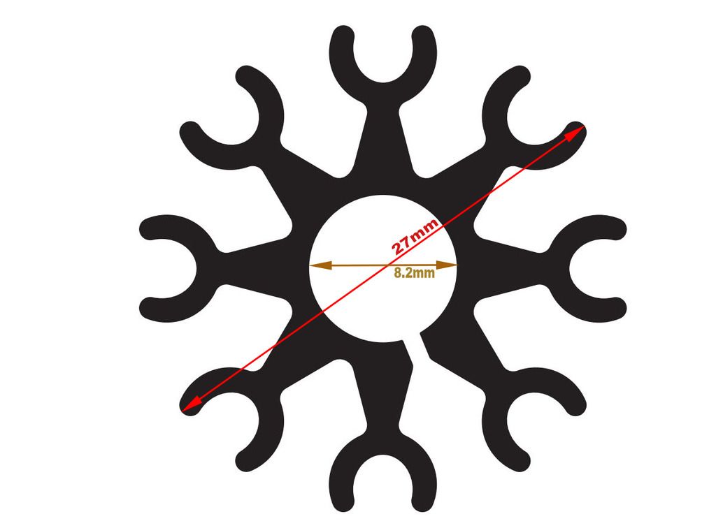
After the tests, I'm starting to recreate the missing heat-sinks for the TO-39 transistors. I'm planning to make a vector image of the originals from my 2230. They look the same to me.
This is the final revision of the schematic (the parts in red are soldered on the back of the board, as it is on the original), I'm attaching it in pdf format too:
After the tests, I'm starting to recreate the missing heat-sinks for the TO-39 transistors. I'm planning to make a vector image of the originals from my 2230. They look the same to me.
Attachments
ton4eff
Active Member
The P700 Board under test:

Everything went smoothly, no surprises... The bias adjusted fine on both channels, after an hour plugged in. It will be adjusted along with the clipping more precise when the board is mounted properly on it's place. And I have to tell you - this thing already SINGS beautiful!
So next to the final step - to39 heat-sinks...


snorbans
Member
I agree, great wok. If you didn't have pins to recycle is there another solution you could recommend?Lookin' good. Are the wire connection post/pins new or recycled?

ton4eff
Active Member
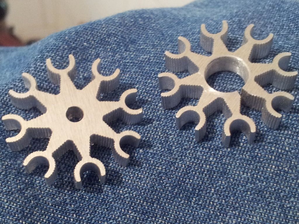
The TO-39 heat sinks arrived. I had to expand the central hole to 8.2mm. I sent the drawing only with 3mm drill, because of the laser cut inaccuracy.
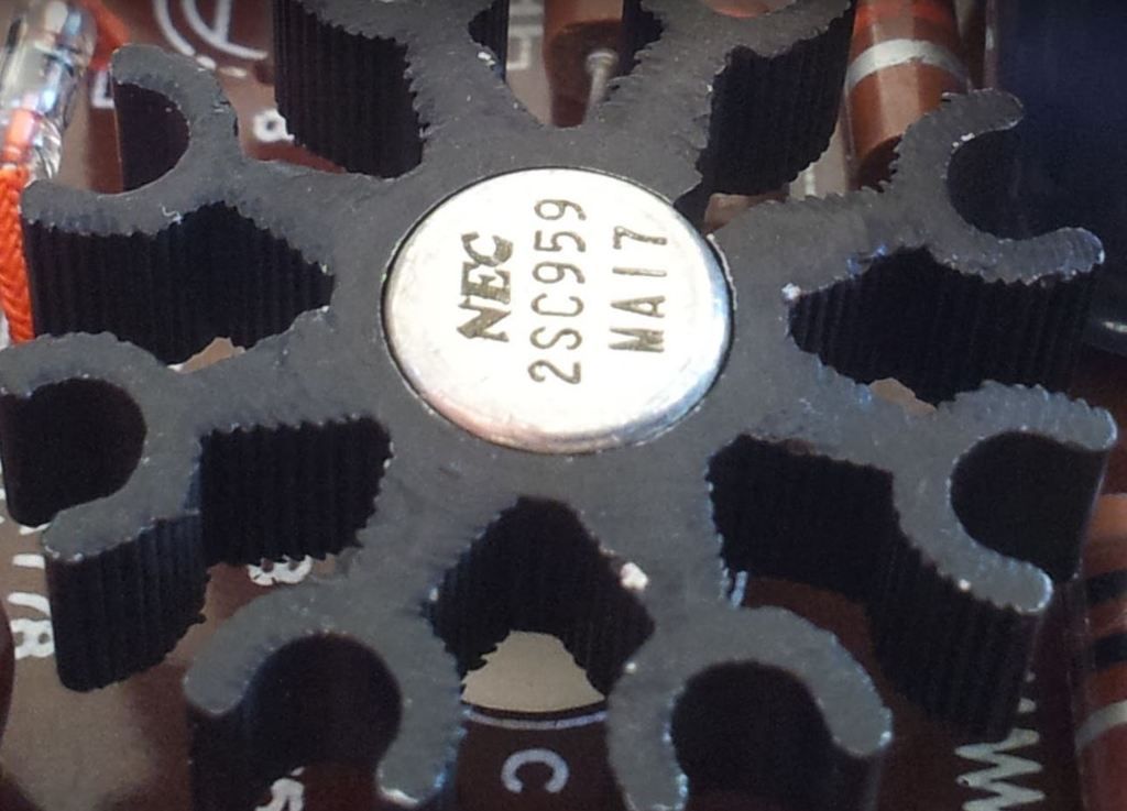
And the two of the heat sinks are already mounted on the transistors. They look pretty much as the originals, don't you think?
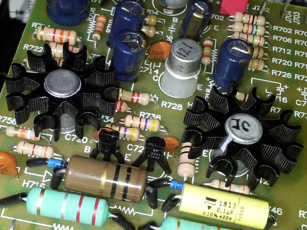
And the two of the heat sinks are already mounted on the transistors. They look pretty much as the originals, don't you think?
Similar threads
- Replies
- 84
- Views
- 5K
- Replies
- 55
- Views
- 2K