Increase of 299C power

How do I adjust it? Seems like the tubes really make the difference. On the HV, I am at 183vdc and 218vdc on the drivers.
Edit: 203 schematic I am now using.
View attachment 1026761
Transformers are hot.
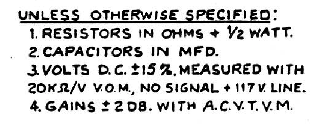
Thank you for listening, it's good to be helpful to someone.
Perhaps before we address the drivers, we should look more at the power supply B+ being high at 510v. Because the other PS voltages are in line with spec, I would think the power tubes are not conducting enough. What is the current power dissipation on the plates? Also, which transformers are hot?
 
What is the current power dissipation on the plates? Also, which transformers are hot?
After all revisions, new voltages are:
new B+.jpg
power dissipation is about 14.5 w, however they drift considerable. Bias is -22.5.

All xformers hot. Outputs are hottest, cannot keep hand on.
 
Last edited:
output tube load actually looks fairly reasonable. I calculate that at 156ma total current draw across the 160 ohm resistor. The rest of the amp uses 21ma so the output tubes alone are eating 135ma, or basically 34ma each.
 
After all revisions, new voltages are:
View attachment 1027188
power dissipation is about 14.5 w, however they drift considerable. Bias is -22.5.

All xformers hot. Outputs are hottest, cannot keep hand on.
On my LK72, the power tx. definitely gets hot after the unit reaches temperature equilibrium. The output txs. also get rather warm mainly because they are so close to the output tubes. How long does it take for them to get too hot to touch?
 
On my LK72, the power tx. definitely gets hot after the unit reaches temperature equilibrium. The output txs. also get rather warm mainly because they are so close to the output tubes. How long does it take for them to get too hot to touch?
Probably 15-20 minutes.
output tube load actually looks fairly reasonable. I calculate that at 156ma total current draw across the 160 ohm resistor. The rest of the amp uses 21ma so the output tubes alone are eating 135ma, or basically 34ma each.
But I had to bias it to about -22.5. Plate is 467vdc and screen is 456vdc. Waiting on new set of tubes as I believe these are weak. I went through a bin full of them; all weak. But for some reason I dont throw them out.:dunno:
 
Last edited:
Probably 15-20 minutes.

But I had to bias it to about -22.5. Plate is 467vdc and screen is 456vdc. Waiting on new set of tubes as I believe these are weak. I went through a bin full of them; all weak. But for some reason I dont throw them out.:dunno:
15-20 mins, something's definitely wrong. Write back when you install the new tubes.
 
The further negative it needs to be to reduce current tends to indicate the tube may be stronger. Not a guarantee but it means that it has enough emission for good idle current production.

Also, see Dave's workup on the 208 which has similar issues. Sounds like Scott's voltages may have just been on the insane side to begin with and you may not actually have anything wrong.
Found the thread. Thanks. Following.
 
In regards to voltage readings on the Scott doesn't the schematic call for a 20k ohm per volt VOM, no signal 117 Line. Also look at the % of difference Scott allows for.. 15% on a 430V spec voltages could be off by 63-64 or so volts higher wow. Anyway, wouldn't using a DMM change the readings a bit? I use the correct meter on my amp rebuilds (a restored Heathkit 20kohm per volt).. I love my Fluke DMM, but it does seem to give a higher voltage reading.
739ef70f7f67f34d5dc5a13d602ae19e.png
 
on the power supply it won't change the reading enough to really notice. The supply impedance is low enough that it won't really be affected by meter loading. Directly at the grid of the power tubes checking the bias voltage may be a different story.
 
As my plate voltage exceeds the max for a 7591 (my 450v vs 400v max on Westinghouse table), I am concerned with damaging a new set of tubes.
As my 299c closely resembles a 208 on the output side with a power supply and pre of a 299c, I overlaid my voltages on the 208 (in red on attached schematic) and they all line up except the plate voltage.
My plate voltage supply line is a 1.2k ohm chalk resistor between the first filter cap and the tube as designed for a 299C (unlike how the 208 derives its plate voltage). Aside from burning up some power and adding some heat, what are the negative aspects of adding an 80 ohm resistor in series, above chassis, to try and get it down some?
299c voltages on 208 schem.jpg
(disregard the highlighting)

Oldman
 
Last edited:
Old -- I'm not sure what data you're referencing for the 7591, but the maximum plate voltage for this tube is 550 volts, while the maximum screen grid voltage is given as 440 volts (Design Maximum Ratings). Also, your plate voltage line is from the rectifier tube, through the 80Ω resistor, through the output transformer primary winding, and to the plates. The screen grids take their power from the junction of the 1.2K and 15K resistors.

Using additional resistance to reduce the voltage is fine, with the understanding that the unit will operate with slightly reduced power output. If you have efficient speakers and don't use (or need) the full power the unit is capable of, then that is a perfectly fine approach to use. The problem with using a resistor (besides the heat) is that the current draw of the amplifier more than doubles on its way to developing full power. Any additional resistance then causes the B+ voltage to sag more than it normally would, which reduces power and increases distortion. Admittedly, avoiding the addition of any extra resistance is likely more important to those who place importance on a given unit being able to produce all of its full rated performance. That is hardly meant as a slam to those who are fine with accepting the somewhat reduced performance that any extra resistance produces. The difference is likely something that could only be shown on test gear anyway, so for most folks, it should and will work just fine, and is a perfectly acceptable solution. It's just that there's a few of us like me who relish every last drop of performance. I think you should go for it and report back the results, which no doubt many folks would find helpful.

Dave
 
If I can, I'd like to jump in on this thread..
I just finished an early LK-72 also. Mine has a hum also, that changes with the volume control it is also in both channels. All can's replaced including a 100/100/100/100@100v from Hayseed Hamfest. For the first section I put a 22mfd (before the first resistor) the second section is 50mfd (after the dropping resistor). Although the 5ar4 is rated at a max of 60mfd I believe. Having the 22 ahead of the dropping resistor and 50 after should be ok. I'm getting about 470VDC at the B+ point to output trannies. All coupling caps have been replaced. Checking with the scope, there is some sawtooth on the first B+ and by the time it gets to the third section down the line it's clean. The negative bias dc is clean at the end of the filter run and voltages are within tolerance.. -48.5 at the end of the filter run. so that's a little over 12vdc to each of the filaments. This is running on normal line power. No Variac. 12ax7 Tubes are a new used set of matched Baldwin branded tubes. The 7199 tubes are RCA Blackplate and test out as good on a Hickok 239a. The outputs are Westinghouse and although not strong test within tolerance and are also known good tubes that were tried in a 299C, they worked fine. This question of the line voltage running up to the switch on the back of the volume control has me curious? The line is twisted as it should be but not a good job of it. Also of note, the hum is much louder when a pair of RCA cables is plugged into the phono input from the Turntable. The amp plays loud and with good frequency response. All voltages are within spec. Tubes all check out.. PS I modified the 5ar4 with diodes. It's a mod I make to almost any amp I have that uses the 5ar4. This helps extend the life of the tubes in the case of a quick start (on then off again). It also could lower the forward voltage a wee bit. So it does seem like the LK72 is plagued with this problem?.. Transformers are cool, no excessive heat. Could it really just be that this power line to volume control is that poor of a design?
 
Old -- I'm not sure what data you're referencing for the 7591, but the maximum plate voltage for this tube is 550 volts, while the maximum screen grid voltage is given as 440 volts ....
Dave
Typo. It is the screen voltage that is high (450v vs 420v design). My info was from this chart however I couldnt find whether max or operating voltage.
upload_2017-10-20_15-43-32.png
I added the 80 ohm but it is insignificant and voltage didnt really change. The resistor added is outside of the B+ chain and branches off the the first filter cap.
Since all my other voltages are fine, is hard on the tubes to run it with these voltages?
299c voltages on 208 schem.jpg
oldman

Edit: Added 470ohm and dropped voltage down a little. If confusing, it is because I am using power supply schematics for a 299c and schematics for output stage are the 208.
screen voltage.jpg
 
Last edited:
If I can, I'd like to jump in on this thread..
I just finished an early LK-72 also. Mine has a hum also, that changes with the volume control it is also in both channels.
Maybe someone with elect. knowledge can help here but just from personal experience with a loud hum that increases with volume on this unit, when I buttoned it up, flipped the plug around and put it on a good source, it went silent.:dunno:

Its loud right now with its belly up and open on the bench.

Just an observation from a parts swapper.

Oldman
 
The screens aren't going to draw a lot of current, so there will be little voltage drop across a resistor in that spot. If you want to drop the screen voltage, increase the value of the 1.2K resistor. It will have a much greater effect.


hum that changes with volume is from the preamp section. Check for missing shields on the tubes, open grounds, or missing covers. Some stuff gets real touchy about that. Could also be noisy tubes, I've had them develop heater-cathode leakage that caused hum. If this has a hum balance, its possible that needs tweaking or the pot is bad. Don't know this model, so feel free to ditch suggestions that don't apply.
Conclusion of my issue:
By changing the 1.2k ohms to 6.2k, I get the screens down to 423vdc. However, the current drops on the output tubes about 20%, from 30ma with the 1.2 ohm/450v, to 24ma with 6.2kohm/423v to the screens.
So, run them with the original 1.5k resistor at 450v or bring the voltage in line and assume weak tubes?
That will about wrap it up for me on this one until I get tubes in.
Thanks all for the help.

Oldman with one last question

and will leave it with PatR
 
Old -- Check to make sure R218 is still good. That is the screen grid bleeder resistor that works to (in part) drop the voltage to the screen grids. If it is open, the screen grid voltage will be high.

That data you are referring to is call "Typical Operating Conditions" data, offered by tube manufacturers as an example of how the tube may be used in practice.

Pat -- So your unit is completely quite with the volume control full down? And even with bottom panel in place, it will hum with an advanced volume control and a high level input selected? Does it hum in both channels?

Dave
 
Old -- Check to make sure R218 is still good. That is the screen grid bleeder resistor that works to (in part) drop the voltage to the screen grids. If it is open, the screen grid voltage will be high.
R218 must have bee a factory option that the original buyer chose not to have installed.
Power comes off the first 60uf cap, thru the 1.2k ohm and straight to the tube without any help. When I got the unit, the 1.2k was also included in the B+ rail but I took it out.
old
 
ah, the missing resistor would explain high screen voltages. Try putting it and the 1.2K back in like the schematic calls for and see what you get. That also creates a bit of extra load on the power supply so it will help drag voltages down at the plate slightly.

Lower screen voltage will result in lower current.
 
Back
Top Bottom