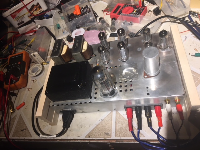
RCA RS177 Low Gain

tonebells

AK Subscriber
Subscriber
I have one of these I am playing around with. I changed the cathode resistors to 4700 (r408/r418) and increased the feedback resistors(r409/r419) to 10K and reduced the 150k input resistors (r431/r432) to 10K. It gave it a little more gain but not enough. I tried an 12AX7 in there but still not great. I think adding a gain stage to replace the one that was in the tuner is the best answer. I have attached the schematic. Anyone willing to share their fix would be appreciated.

Tony
 

Attachments

  • 64_RCA_RS-177H_134.pdf
    222.4 KB · Views: 63
I was just speaking with my tech/buddy today about what he did to my RS177 the reason being is I have another AK'er who was inquiring about mine.

He added a pair of 6AV6's and an additional circuit, a pre amp circuit? if I understood him correctly. I'm not sure exactly what he did but it sounds great and I barely have to turn it up.

Here's some pics of what it looks like, not the best picture of the underside but hopefully it helps.


index.php


index.php


index.php
 

Attachments

  • DSCN1255.JPG
    DSCN1255.JPG
    161.6 KB · Views: 129
  • DSCN7868.JPG
    DSCN7868.JPG
    77.1 KB · Views: 120
  • DSCN7869.JPG
    DSCN7869.JPG
    72.6 KB · Views: 119
In stock form it uses half of a 6FQ7 in the preamp per channel to get enough gain to be useful. Copy the stage immediately upstream of the 6FQ7 tube on the amp chassis and it should be fine. Put the feedback at stock levels again or it will probably be obnoxious.
 
H-K style positive feedback is one way to increase gain (and keep the 6FQ7). 12AX7 will also do it, with appropriate resistor value changes.
 
I converted an RCA console amp, model 183A, to standalone service. The 183 is a three channel amp on a single chassis but otherwise similar topology to the 177. I had the same problem--not enough gain on the stock power amp chassis to drive it directly from an iPhone.

So I converted it to a two channel amp utilizing the same stock frontend tubes (6CG7), and at the same time gave it more gain by swapping out the split load inverter (aka cathodyne) for the cathode coupled differential pair (aka long tail pair).

That nailed the gain problem. Sensitivity is now 0.4V input for full power output--perfect for an iPhone input source--and really quiet to boot. Note however because the forward voltage gain of the amp changed significantly with this mod, I had to basically retune the amp from scratch. That included resetting the feedback resistor value and associated feedback capacitor, as well as I added a HF tuning network that wasn't there in the original amp.

Just an idea of another way to solve yours, if you don't mind getting knee deep in the rewiring.

If you want to read about what I did, it is here.
 
Just a caution about feedback style changes, you'll want to make sure it doesn't get unstable. Its a very fine line between an amp with a feedback circuit and an oscillator.

I do wish the various i-devices had better output. I use my iPod a lot as a background music source and my relatively low gain preamp doesn't quite bump it enough to get full power. My little German console amp has pretty high sensitivity, somewhere around 0.4 volts, and it does very nicely with it though. No preamp required.
 
All of the resistors I have replaced so far have been pretty high. So I will be in deep anyway.
 
I added a 6FQ7 with jumper wires and it plays as loud as other amp with my test speakers. I will draw it up for review.

Tony
 
Interested in whether this idea of copying the circuit from the tuner-pre worked out!

Proud new RS177 owner here.
 
Here is my guess at it. Let me know what you think.

Tony

View attachment 950538

I used your schematic as starting point but unfortunately AFTER I did various other changes to add gain mentioned in another thread. Overall the rig sounds pretty good and adding a third 6FQ7 did solved the gain issue for me. My power supply looks pretty different than stock. The stock 100 Ohm dropping resistor resulted in 400 Volts B+ so I'm running an aluminium 470 Ohm 100W resistor that is chassis mounted. The first cap after the rectifier is smaller (47 vs 80 which is in-sync with the tube data sheet). All other caps are 120 instead of 80. Bias resistors for the EL84s are 330 instead of 110 which results in 340V plate voltage @ 20 ma. One small issue: If I push the volume to more than 70% I get distortion on both channels that slowly kicks in and gets worse with more volume. I assume that this is due to the other changes that I did to the circuit. I have some time tomorrow to roll back the other changes - in particular the removal of the resistors after the coupling caps (which was mentioned in another thread). Once everything is perfect I might post the full schematic :)
IMG_2140.jpg
 
Back
Top Bottom