I installed the EOS PS last eve. Let me first thank Kevin for posting his documentation.
My Experience:
My first impression of the EOS unit is that it feels much lighter in weight than the stock (MC-12) model. Of course my original unit is encased in a metal/aluminum enclosure that I presume acts as a heatsink and protective frame. The enclosure also provides some sort of thin, antistatic and/or solder joint protection barrier the sits between the enclosure and the bottom of the circuit board. Interesting that this piece of plastic or whatever it is composed of does not cover the entire under surface of the board. The underside of the EOS unit is 100% exposed. Not ideal IMHO. However, following Kevin's lead - the recommended standoffs supply ample space between the bottom of the circuit board and the facing mounting area on the chassis panel. By the way I did not remove the mounting panel. I was able to carefully lower the wired PS into the installation area with no problem. The exposed, threaded ends of the four standoffs easily inserted into the pre-existing mounting holes on the chassis panel. And yes - it's great that these supplied holes perfectly match the EOS PS.
The Molex modification using the new connector did not work for me. First, after removing the wires from the existing Molex connectors (there are 2) - I noticed the small, sort of spring locking contact wire connectors were not the same as what Kevin displayed in his pic. I was
unable to securly seat the repositioned wires in the new Molex connector. I tried bending the pins, re-shaping, etc. No luck. I attempted to leave the connectors loosely positioned inside the new Molex, hoping that the PS pins, when inserted - would tighten things up thus securing the loose inside wire connectors. The problem with this approach was that the holes in the new Molex connector along with the loosely seated wire connectors made it extremely difficult to seat the Molex on the PS pins.
I decided to revert back to the original Molex (x2) connectors. My thought was the wires would fit more snugly after proper re-positioning. Keep in mind the EOS board supplies 12 pins. The stock PS supplies 13.
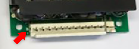
In the pic below of the EOS unit, notice the gap between the left end of the pin area and the circuit board mounting hole. This gap effectively enables the use of the existing Molex connectors by simply ignoring the first/left side wire insertion hole on one of the original Molex connectors. The unused hole on the Molex overhangs and occupies the noted gap. In this configuration, I successfully seated the properly re-positioned wire connectors inside the original Molex connectors (x2) and seated them snugly on the EOS unit's pins.
Reminder: The use of the existing Molex (x2) connector still requires wire reconfiguration for EOS unit compatibility.
As far as the necessity to invert the wires inside the power/line feed connector, this is true. I did this, hoping I would not have issues when attempting to securely lock the repositioned wires. I was successful here. It worked as expected. One note - the color coded (brown/blue) wires have interfacing female blade connectors that are secured to male blade connectors located on the opposite side (located inside the MC-12) of the A/C plug connector that feeds external power to the unit. Theoretically you can simply disconnect the blade connectors and invert them, in which case you would not need to flip the placement of the wires inside the PS connector. I elected NOT to do this, simply becuase I would be compromising the color coding consistancy between the male and female blade connectors that receive/pass the external power.
That's about it. Aside from the slight delay caused by my inability to use the replacement Molex connector - this modification is straight forward. I think I've heard "authorized" techs charging $500-$600 to replace the PS in these units, plus added shipping costs? Absolutely crazy and totally unnecessary. If you are careful and can handle a screwdriver - you should be set. I paid $100 for the new EOS PS (including tax and expedited delivery). I purchased it from Sager Electronics.
Finally, I'm not concerned about the internal fan and it's compatibility. I'm installing a fan above mine. It will be controlled by some sort of timer or programmable smart outlet for intermittent cooling.
-paul.
@produceNewMedia


") . In all seriousness they sell (I would estimate) for upwards of $1500. Of course it depends on it's functional and cosmetic condition.
. In all seriousness they sell (I would estimate) for upwards of $1500. Of course it depends on it's functional and cosmetic condition.