Bob Latino Dynaco ST 70 amp build

Nice, I bagan putting one together but I haven't worked on it much lately. I didn't get the Russian PIO's. I got a set of Orange Drops 716's. Not sure if I'll switch. I have PIO's in the other two amps I assembled.
 
Do put an isolation layer around the "russian caps" on the underside of the board.
 
Do put an isolation layer around the "russian caps" on the underside of the board.

A isolation layer? I know how I could do that too. I do resin casting. I make 1:24/1:25 Scale model car parts. I could create a dam around these Russian caps. I would mix and pour a small amount of silicone in the damn and then it would cure. I would be using a platinum silicone. The Mold Star 30. Anybody think this is not a good idea? Otherwise, I am uncertain how to isolate them.
https://www.reynoldsam.com/
https://www.reynoldsam.com/product/mold-star/

http://smcbofphx.proboards.com/board/45/resin-casting Here is some of my model car parts making. Silicone and resin is an amazing world!
 
Last edited:
Take your time, double check your work periodically and FOLLOW the instructions!!!!

Get a magnifying glass and check the solder joints on that board. Those solder pads are small and can easily cause a problem if not done correctly.

I built that amp a few years ago and I'm still VERY impressed with it. Get the GL KT-88 output tubes and a EH 12BH7 center and 2 TungSol 12AU7 outer tubes and it's party time!!!

Keep posting the pictures
 
Finished? Not so fast ...

One nice feature of the VTA boards is that the solder pads are double sided. Lot better strength and longevity if you solder both sides. Pay close attention to the tube sockets as those can take a pretty good pounding over time, especially if you're a tube roller. I also give each leg a slight twist after setting the socket into the board to get as tight a connection as possible before soldering.

vta-board-top.jpg


Also, the PIOs look a bit tight to the board. One potential problem with the metal cases is they can short to a hot circuit. Make sure any component leads near the cases are trimmed short, and maybe add a strip of electrical tape between the caps and board, and you should be fine.

Also make sure you trim any component leads around the edges of the board, and double check clearance when you install it in the chassis. Not uncommon for shorts to happen there also. Worth remembering that even if there's no hard contact, voltage can arc under load.

And ... mostly just pay attention to the directions. Bob & Co have an outstanding step by step guide. I check the items off one by one, and highlight all the "solder later" steps I see. Once the kit is done, I go thru the list one more time, checking each item again for insurance. DO follow the first start instructions as well. And have fun!
 
A isolation layer? I know how I could do that too. I do resin casting. I make 1:24/1:25 Scale model car parts. I could create a dam around these Russian caps. I would mix and pour a small amount of silicone in the damn and then it would cure. I would be using a platinum silicone. The Mold Star 30. Anybody think this is not a good idea? Otherwise, I am uncertain how to isolate them.
https://www.reynoldsam.com/
https://www.reynoldsam.com/product/mold-star/

http://smcbofphx.proboards.com/board/45/resin-casting Here is some of my model car parts making. Silicone and resin is an amazing world!
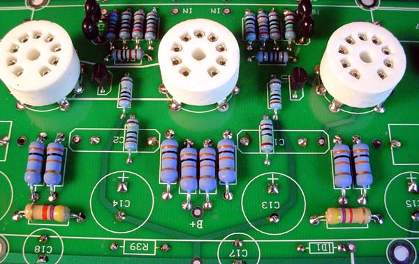
A cardboard strip under each is enough. Or put each cap in a crimptube before mounting. Just make sure that
the caps outer metallic surface won't touch the board.
 
Thank you for the info. The pictures of the circuit board are old ones. I put the leads of the Russian caps in the wrong holes but corrected them.new 70 3.JPG new 70 4.JPG
I purchased a can of Rustoleum paint. It is hammered copper. I was going to go with some other color but I liked it.
 
Take your time, double check your work periodically and FOLLOW the instructions!!!!

Get a magnifying glass and check the solder joints on that board. Those solder pads are small and can easily cause a problem if not done correctly.

I built that amp a few years ago and I'm still VERY impressed with it. Get the GL KT-88 output tubes and a EH 12BH7 center and 2 TungSol 12AU7 outer tubes and it's party time!!!

Keep posting the pictures

Finished? Not so fast ...

One nice feature of the VTA boards is that the solder pads are double sided. Lot better strength and longevity if you solder both sides. Pay close attention to the tube sockets as those can take a pretty good pounding over time, especially if you're a tube roller. I also give each leg a slight twist after setting the socket into the board to get as tight a connection as possible before soldering.

vta-board-top.jpg


Also, the PIOs look a bit tight to the board. One potential problem with the metal cases is they can short to a hot circuit. Make sure any component leads near the cases are trimmed short, and maybe add a strip of electrical tape between the caps and board, and you should be fine.

Also make sure you trim any component leads around the edges of the board, and double check clearance when you install it in the chassis. Not uncommon for shorts to happen there also. Worth remembering that even if there's no hard contact, voltage can arc under load.

And ... mostly just pay attention to the directions. Bob & Co have an outstanding step by step guide. I check the items off one by one, and highlight all the "solder later" steps I see. Once the kit is done, I go thru the list one more time, checking each item again for insurance. DO follow the first start instructions as well. And have fun!

SO....I should solder on both sides?
 
More of a solder one side, then flip the board and solder the other rather than trying to flow both sides at the same time. Hot gun properly tinned and used correctly won't damage components done like that. Nothing all that delicate here anyway, except maybe the CSS transistors? Beefy boards too, so no worries about lifting traces.

Your call.
 
Take your time, double check your work periodically and FOLLOW the instructions!!!!

Get a magnifying glass and check the solder joints on that board. Those solder pads are small and can easily cause a problem if not done correctly.

I built that amp a few years ago and I'm still VERY impressed with it. Get the GL KT-88 output tubes and a EH 12BH7 center and 2 TungSol 12AU7 outer tubes and it's party time!!!

Keep posting the pictures

I already have a brand new set of EL34's and I purchased 3 matching 12AU7 tubes. I did follow your advice. I purchased a quad set factory matched and supposedly a 24 hour burn in for $130.00 and free postage from a Ohio seller on Ebay.

https://www.ebay.com/itm/QUAD-Electro-Harmonix-Factory-Matched-KT88-KT88EH-Vacuum-Tubes-24hr-Burn-in/312031375230?ssPageName=STRK:MEBIDX:IT&_trksid=p2057872.m2749.l2649

Hopefully it was a good deal. I viewed some listings that wanted more than this for one tube. Can't go wrong with a EH tube.

https://www.ebay.com/itm/1x-NEW-Ele...e=STRK:MEBIDX:IT&_trksid=p2057872.m2749.l2649

Also purchased one of these.
 
Last edited:
Solder both sides, that's why they sell soldering heat sink clamps.
The copper traces can be on the component side, the other side or both. So it's best to solder both if you can.

Planning helps. For example, if a large cap is going get in the way and make it difficult to solder a small resistor..do the small stuff first and build from the center out.
 
I already have a brand new set of EL34's and I purchased 3 matching 12AU7 tubes. I did follow your advice. I purchased a quad set factory matched and supposedly a 24 hour burn in for $130.00 and free postage from a Ohio seller on Ebay.

https://www.ebay.com/itm/QUAD-Electro-Harmonix-Factory-Matched-KT88-KT88EH-Vacuum-Tubes-24hr-Burn-in/312031375230?ssPageName=STRK:MEBIDX:IT&_trksid=p2057872.m2749.l2649

Hopefully it was a good deal. I viewed some listings that wanted more than this for one tube. Can't go wrong with a EH tube.

https://www.ebay.com/itm/1x-NEW-Electro-Harmonix-12BH7-EH-Gold-12BH7EH-12BH7A-Vacuum-Tube-GOLD-TESTED/290637902632?ssPageName=STRK:MEBIDX:IT&_trksid=p2057872.m2749.l2649

Also purchased one of these.
A VERY reliable source of tubes, and a heck of an honest and knowledgeable guy is Jim McShane. http://www.mcshanedesign.net/tubes.htm

Post some pics as you proceed with your build. We still enjoy seeing them.
 
I finished putting the amplifier together. It might not be the prettiest inside but it does sound really good. I am frustrated that for some reason I can't seem to adjust the bias on the right channel. It seems strange that the meter seems to function properly on the left channel but not on the right channel. It is a radio Shack meter that I have had for several years.new 70 7.JPG new 70 5.JPG new 70 3.JPG

I do have a question about using this amp in mono mode. I have had stereo 70's before. I originally had two in mono mode by putting the switch on mono. If I purchase another does some rewiring need to be done or should I just purchase two mono amp kits to start new?
 
Last edited:
Are there ANY readings on the right channel? Make sure you are using the correct contact points.

Go back and read the instructions sheet. Check EVERY step no matter how small and silly to make sure the wires are connected to the proper points. Also check to make sure you installed the bias pots in the correct position. All four tubes have separate bias so I can't imagine how the entire right channel has no bias voltages. I would recheck the proper placement and parts of components and or board.

Did you also contact Bob. I
 
You might want to try swapping the power tubes between the 2 channels. See if the bias issue moves to the other channel. Seen a similar situation that was related to the inconsistency in new Russian Tung sol tubes. Its an easy 1st step for process of elimination.

The copper color of the transformers looks really nice. Restored a few ST70s and built a kit as well. Nice job!

The amps I have do not require matched tubes, however the inconsistency in the KT120s from the manufacture has been so wide, that the amps now come with matched sets of tubes.

Now using matched sets, as a way to get quality control that is lacking in the factory tubes otherwise.

Not to say you have a bad tube, but its a quick way to rule it out.
 
Last edited:
The bias issue seems to be with the meter. I have used it very little and attempted to refer to the manual for it. I have the tubes dialed in to .499 to .502. It will take some breaking in and the bias will be checked often. I did as a member suggested. I have a 12BH7 in the middle and 12AU7 tubes outboard. I am uncertain of the reason but it does sound good. I am now wanting to rebuild the crossovers in my original Grafyx SP10 speakers. What I really need is a good room to have the stereo set up in. I should have that in a year or so.
 
IMG_1251.jpg Nice work. I have a vintage ST70 that was rough and pitted badly. Cleaned up the chassis and painted a copper color similar to your trannies. Nice vintage color. Its just a stock type board from Dynakitparts with adaptors for the 7199s. Like to hear one like yours. This one looked like it was in a damp basement for decades. She sings again in hammer tone copper.
 
Last edited:
Back
Top Bottom