CA-303 comes to the Lab for some TLC.

Thanks Mano. I have seen conflicting tube orders in the past. I have to look at the Service manual again. When my japan unit showed up it was different than the manual. Unless I was reading it wrong LOL
 
View attachment 1234500
Hi Kev,
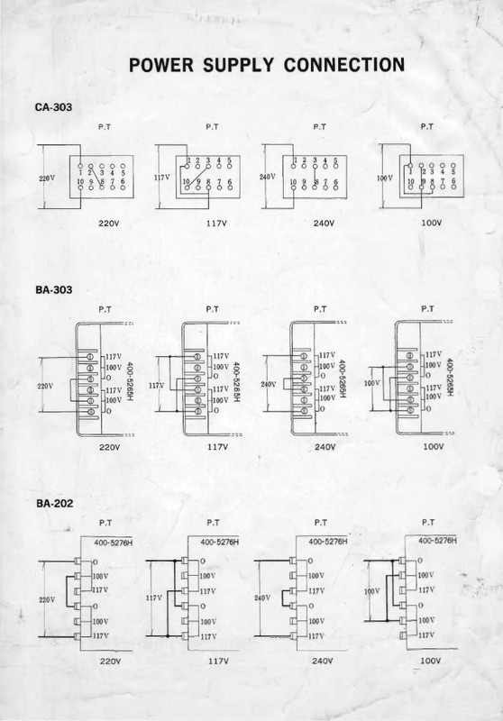
Just got hold of a CA-303, today, Japanese model set for 100V. Tons of work to do, including the phono connectors being changed, however, looking at the underside of the transformer there is a 10pin block exactly like mine. Pin 10 has nothing connected on it on mine, and if its the same thats on your bench, may be possible to convert the 100 to 240V AC. Initially with the primary strapped for 100V, I read just about 9Ohms, Once I snipped the strap between 2 and 9, I can now read 18Ohms between 1 and 2 and similar between 8 and 9. 3 Ohms between 2 & 3 similarly between 9-10.
To me looks like the CA-303 JDM models can be strapped to 240, avoiding the step-down transformer or having the transformer rewound.

You are right:

 
You are right:


Funny this should come up, as I was plotting out what I will do with the Multi-caps, I was looking at that block thinking exactly the same thing about it being able to change it to 240V.
I will ask the customer if he wants me to change it.
Remember this is a customer unit, not mine.

Whilst its an interesting unit, its not my thing really, I am not a tube guy....

Thanks Mano. I have seen conflicting tube orders in the past. I have to look at the Service manual again. When my japan unit showed up it was different than the manual. Unless I was reading it wrong LOL

There's nothing conflicting Rick its very clear in the manual as to where the tubes go. The metal cans go over the high gain tubes which is correct in the picture.
 
including the phono connectors being changed
Yeah those connectors are the old type RCA which are wider, they really all need to be changed.

Thanks for the tip on the transformer wiring, this is what I was thinking when I was looking at that block las week..
I've asked the customer if he wants to change it to 240V, will see what he says.
 
On the Multi-section caps, I am planning to cut it 5mm above the base, and reuse the housing. `Lets see how it goes..
 
There's nothing conflicting Rick its very clear in the manual as to where the tubes go.[/QUOTE]
Yes. I installed the tubes per manual. The prior owner had them installed incorrectly. Online pics showed conflicting tube orders. LOL.
 
There's nothing conflicting Rick its very clear in the manual as to where the tubes go.
Yes. I installed the tubes per manual. The prior owner had them installed incorrectly. Online pics showed conflicting tube orders. LOL.[/QUOTE]

LOL the internet experts at it again!! :yikes:
 
Wired for 240VAC now......:yikes:
I think what I am going to do with the capacitor situation here is to remove the two tag boards, chop the pins off the multi-caps, and mount the new caps on perf-board with the resistors and everything, and then use the screw holes for some nylon stand-offs and leave the multi-caps in place for authenticity, should be able to make it nice and neat....
That will be next week when the caps turn up.
The owner is not in a hurry to get it back, so I can take my time with it...
I will also fit a new 3 core cable and plug which will earth the unit, its only got about 30VAC leakage on the chassis which it pretty good for a tube unit...but I insist on earthing these things now, all of them, everything I work on now, out goes the two core and in comes the three core!!
IMG_6547.JPG
IMG_6551.JPG
 
Yes, its cramped in the PSU section, all on a perf board, good idea.

I am working on the phono sockets, while waiting on parts. As the unit is mine :banana:, the plans are
a) Changing the Phono sockets at present.
b) Re-route the Phono 1 - to use the Microphone Transformer plugin for MC-pickup.
c) Change all the Oil and Electrolyte caps
d) Work on the PSU section.
e) Convert to 240V, + Suppressor to the Power switch.
f) May be to use IEC C14 socket in the place of the un-switched outlet and the next one above and blank out the current mains cable hole.
luckily the oil caps have already been removed from this one so thats good!!
Looks like a solid plan you have there...
 
Hi Kev,
Rebuilt the PSU section on a 90x100mm perfboard. (cannot seem to insert the snapshot as attachment) .Using metal film resistors eats up lot less space. All connected and when powered up, humming and motor-boating.
Long story short, one of the tag-strips on the old PSU layout grounded the -ve supply of the PSU section to chassis. This Grounding comes into play for the front of the pre-amp section, V601,2,3,4,5,6. Spent good 2 hours, chasing my tail.
As the perf board is tight for space, the 20-Ohm 10W, on the board is not a good idea, so will replace that with a aluminium panel mounted version. Getting too hot..

Mano
p.s: Good call on the perfboard.. so much better, thanks
 
Hey Mano,
Nice work, I have been getting distracted and keep forgetting to come back to this.
I have also finished my PSU.
I left that 20W resistor mounted where it was, it fits snug in the corner against the chassis using it as a heat sink.

I was trying a few different ways of mounting it, and got it upside down, Caps on bottom and the resistors on top.
I used the original resistors.
I was pretty happy with the way it turned out.
I went for the Fender Twin style layout....lol....
Also used a couple of nylon stand-off's to mount.
IMG_6576.JPGIMG_6577.JPGIMG_6578.JPGIMG_6580.JPG
 
Back
Top Bottom