

You are using an out of date browser. It may not display this or other websites correctly.
You should upgrade or use an alternative browser.
You should upgrade or use an alternative browser.
1980 FM tuner dead
- Thread starter jtee1340
- Start date
Hi txturbo,
It is nice to see that you can confirm that your ckt is working properly.
While you are at it, tune to a part of the dial where all you hear is white noise, see what your meter reads to determine if you quad coil is centered, see if it is in proper alignment.
BTW how easy is it to access the lower core slug? without going through the top. If you have go through the top you will have to move the top slug which will throw that off.
I suggest if you have to go through the top, determine how much you turn the bottom slug, then once centered move the top slug back to where it was initially. Or if you have the proper low THD RF SG equipment, you can adjust the top slug for lowest THD.
I think before he changes U4 (PA3001-A), that he should try to see if he can adjust the quad coil for center. Lets hope that is all it is, so he does not have to do what you are suggesting.
We have no idea if there is something wrong with the quad coil, it could be a broken slug or something else as well
I have not done the test/experiment to see how far you can de-tune the circuit and measure what the resulting AFC offset V would be. Not sure if you can de-tune it that much to get the V that he is measuring.
The unit is at work, I can do some more testing tomorrow. I could detune the circuit but I need to set up all of the test gear again. If you think of anything else to test let me know. It's kind of fun to do remote diagnosis, Apollo 13 like.
FYI... I just did an alignment on this receiver. You can get to the lower slug with the right tool, it needs to have a shaft that is skinny with a small adjustment head. You need to work it gently to get it past the first core into the second one. Surprisingly the upper core does not move. If I remember the board has a hole in it to allow you to get to the lower slug through the bottom if need be. I was able to do it from the top. I will take a picture of the tool I used. If I remember the top coil is the last one you adjust for THD so it's not really a problem.
The unit I was working on had poor signal sensitivity, signal strength jumped all over when tuning and the fine tune would light up off center, then when you let your hand off of the dial it would center when the quartz lock lit up. I could only get a couple of stations to tune. Cleaning the tuning cap solved the jumping of the signal strength. Small adjustments to the trimmer caps on the front end brought the sensitivity back up, I did not touch the coils. To get the center tuning working properly I needed to adjust the upper and lower discriminator core. I had to do it a couple times to get the tuning on center with fine tuning led. The distortion was something like .2% if I remember.
I thought that he did not have a generator and distortion meter, that's why I suggested trying the chip. It seems like the voltage to the center tuninng meter is way off.
Hello Guys,
Well I appreciate the insight you both are providing. It has been a great help.
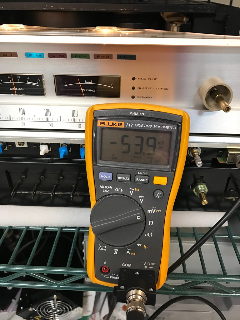
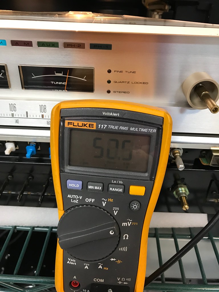
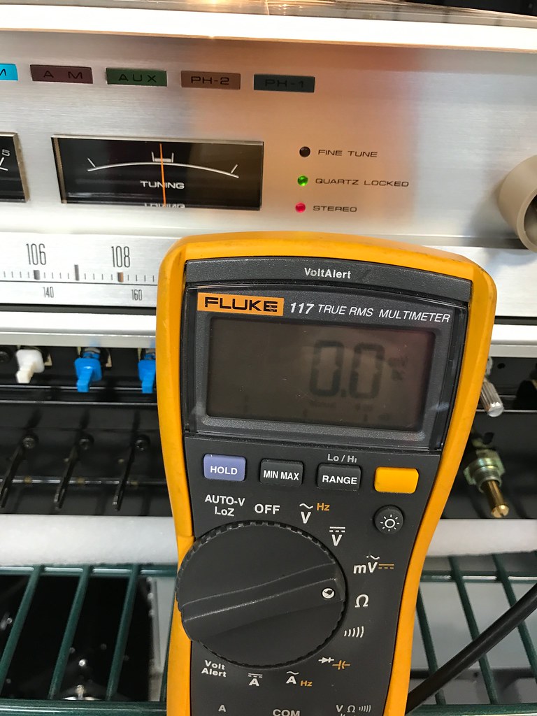
I took DC voltage measurements with 650 ohms across pins 30 and 31 to simulate the meter load. The readings were between 25 and 200mv as I tuned. Thing is, they never went negative at all.
I got the alignment tools delivered and I there are a couple that seem to be possible to get to the lower coil.
I am going to try adjusting the lower coil and see if it adjusts.
Will report back.
Thanks,
J.T.
Well I appreciate the insight you both are providing. It has been a great help.
I took DC voltage measurements with 650 ohms across pins 30 and 31 to simulate the meter load. The readings were between 25 and 200mv as I tuned. Thing is, they never went negative at all.
I got the alignment tools delivered and I there are a couple that seem to be possible to get to the lower coil.
I am going to try adjusting the lower coil and see if it adjusts.
Will report back.
Thanks,
J.T.
Well, I was able to adjust pin 7 down to within a volt or so of the bias voltage of pin 10. However, as I adjusted the station seemed to fade out. I brought it back to about where it was and the station came back stronger.
Seems to me that the adjustment was were it needed to be before I adjusted?
I could not get it totally down to match the bias voltage before the tool started to slip. Didn't want to damage the core so I didn't force it. I am starting to think the chip is the culprit.
What do you think?
J.T.
Seems to me that the adjustment was were it needed to be before I adjusted?
I could not get it totally down to match the bias voltage before the tool started to slip. Didn't want to damage the core so I didn't force it. I am starting to think the chip is the culprit.
What do you think?
J.T.
The tool is undercut along the shaft, the shaft diameter is smaller than the last 1/2 inch or so of the adjusting hex tool.
Initial discriminator adjustments (center tuning) are done with DEAD AIR. Due to the sensitivity of this beast, that can be hard to arrange!!
Initial discriminator adjustments (center tuning) are done with DEAD AIR. Due to the sensitivity of this beast, that can be hard to arrange!!

Thanks for the clarification Mark.
I have the IF input to chassis ground and 330 ohm resistor between ground and PIN 35 as Rick suggested.
My question is, should I still get FM station tuned when I short IF input to ground?
I do not get white noise like you are talking about. Do I need to detune off the channel? Maybe the station is to strong?
You said it may be hard to arrange do to sensitivity, so it may pick up the station with IF shorted to ground?
txturbo,
I appreciate the extra effort to show working circuit!
Thanks,
J.T.
Thanks,
J.T.
I have the IF input to chassis ground and 330 ohm resistor between ground and PIN 35 as Rick suggested.
tie the IF input pin 34 to ground,pin 35 with a 330 ohm R to make sure there is no RF IF signal to do the quad coil centering adjustment.
On the pcb pins 30,31 are your afc ckt measuring points
Good luck.
F9 has nothing to do with FM operation, it is the AM IF filter.
My question is, should I still get FM station tuned when I short IF input to ground?
I do not get white noise like you are talking about. Do I need to detune off the channel? Maybe the station is to strong?
You said it may be hard to arrange do to sensitivity, so it may pick up the station with IF shorted to ground?
txturbo,
I appreciate the extra effort to show working circuit!
Thanks,
J.T.
Thanks,
J.T.

A worthy try rcs16, but dead air isn't that easy. It remains a quest with me on how to do it in a non-invasive manner.
Pin 36 on the tuner is an OUTPUT of power to the front end. After the 13v powers the pa3001, then the IF stages, it goes out to the tuner (FM front end) on pin 36.
And if you look for the (FM only) front end in the manual - it isn't in there - Pioneer just bought the FM front end, they didn't make it.
Just for a definition of the front end, it is the RF gain stage, the local oscillator and the mixer and then the IF transformer.
And any AGC, AFT or the special APC circuits / inputs / outputs.
And it looks like the IF killer input on pin 32 shuts down more in the chip than just the IF stages.
Yeah, it was a leap to see if the IF killer would do the trick, keep trying til we get it right.
Okay, I thought of another method to try for a white noise source, as before,
Select FM,muting off, tune to a quiet part of the dial, usually at the far ends,
With power off, tack solder a 1nF ceramic cap with very short leads, across R12(330) onto its leads. See if that does the job.
And if you look for the (FM only) front end in the manual - it isn't in there - Pioneer just bought the FM front end, they didn't make it.
I see it (AWB-030) drawn on p50 of the manual. There is no parts list, so it could be that it was built by another mfg. They say their is nothing to service and that you should change the whole unit out but I do not agree that certain items can not be repaired.
Last edited:
Well partial success. I went ahead and swapped out the PA3001a chip with the other tuner board. It had been soldered on before so....
Anyway, I now have signal strength meter working, but the tuning meter goes off to the left about half way and sets there.
It does not react to turning the tuner knob. I tried to adjust the coil just to see if it would affect the needle and no. it did not.
I don't know the condition of the chip I pulled out of the other board so I am not sure if that chip was good or not.
So I went out looking for Pa3001a chip. I see many on EBay, but doubt if they are real.
I see that the HA11225 chip is actually a sub for the PA3001a chip on the Pioneer web site. http://parts.pioneerelectronics.com/part.asp?productNum=PA3001-A
Has anyone tried to get a replacement for this chip? Where did you get it?
I wonder if the HA11225 will work?
Any insite would be great.
Thanks,
J.T.
I have not try to get any PA3001 replacements, nor have I tried a HA11225.
which source for a PA3001 are you considering? If it is only $4 not too much to lose.
If I had something that used a PA3001 I'd try out a HA11225, as I have one in a Crown FM2 tuner.
I think we can say that if the replacement PA3001 part from the other pcb makes the signal meter indicate, that the original PA3001 is toast.
I hope that you installed a IC socket to make it easy to change parts.
Now is it the chips or something else, certainly would not hurt to try out another chip.
I am not sure if a HA11225 is similar enough to a PA3001 to be used as a sub. Only one way to know, try
One idea, is to put the PA3001 back in the doner pcb, power it up to see if you can get it to zero the discriminator(center the meter). See if it acts the same.
All you need is a 13V power supply and a few wires/clips, basically make a test jig.
Did you get any audio out of the replaced PA3001 from the doner pcb?
Fun wow, progress is slow but i will stick with you to the end. It is a challenge to trouble shoot these.
Rick,
I did not have a 16 pin socket to install at the time. I have one now and wished I had used it. The Pioneer site I referenced above is where I got the info that HA11225 chip is a sub for the PA3001. Don't know if I can order directly from them or not, as they ask you to log in.
The price of their Ha11225 chip is a lot higher also. It looks like it redirects you to PAC parts and they say not in stock.
After examining the board from the parts unit, I am starting to think I went the right direction and trying to fix this one. It has a lot of evidence of work done on it.
Yes, I did have audio that played fine.
txturbo, I may take a chance on overseas vendor, but I am still searching.
Thanks,
J.T.
Last edited: