

You are using an out of date browser. It may not display this or other websites correctly.
You should upgrade or use an alternative browser.
You should upgrade or use an alternative browser.
2270: No bias?!
- Thread starter quadtech
- Start date
Those big green resistors - they are 10ohm, 10W wirewounds,
connected between the bridge rectifier's + and - and the big, main
filter caps. Like so -
Bridge Pos Lug --> 10ohm,10W --> fuse -> Filter cap
Bridge Neg Lug --> 10ohm,10W --> fuse -> Filter cap
The wiring looks like original Marantz, with the correct red and
yellow color code and well soldered.
The fuse holders are screwed down to the chassis near the filter caps.
The resistors check out good at about 10.5 ohms each.
With these in place, I see 45-0-45 V on the filter caps under load.
I finally found time to get back to my amp today.
Started with the right channel and I measured all the
resistors on the board.
Most seem alright, but there are a few deviations.
This may be due to drifting, or errors of measuring them in-circuit.
(My multimeter seems to have issues reading very low value
resistors like the 0.2ohm ones.)
Measurement results are attached.
Ecluser : R786 is good at 100 ohms.
I found that the previous tech replaced the following -
2SC484 at H757 with a SL100
2SA464 at H756 with a SK100
Zeners H764, H765 seem good too.
I have the heatsink and outputs disconnected.
Is there any further testing I can do without the output transistors?
Attachments

Last edited:
Folks, if anyone is watching this...
I measured all the resistors on the left channel too, and got
practically the same readings as the right channel.
The only thing I see different from a stock board is that both channels
have the flowery heatsink transistors replaced as below -
2SC484 at H757 with a SL100
2SA464 at H756 with a SK100
Could this cause the bias issues at the outputs?
My local vendor got me 2N3440s for 2SC484, but
does not have 2N5415 (or 2N5416) to replace the 2SA484.
I'll try and search around this week, and also look
for the ones recommended by Echowars elsewhere - 2SC2690
and 2SA1220 (with a different case style).
Would any of these other alternatives be suitable subs? (I know
they are a different case style).
MJE340/MJE350?
2SD669/2SB649?
TIP30, TIP29?
Suggestions/opinions welcome...thanks")
I measured all the resistors on the left channel too, and got
practically the same readings as the right channel.
The only thing I see different from a stock board is that both channels
have the flowery heatsink transistors replaced as below -
2SC484 at H757 with a SL100
2SA464 at H756 with a SK100
Could this cause the bias issues at the outputs?
My local vendor got me 2N3440s for 2SC484, but
does not have 2N5415 (or 2N5416) to replace the 2SA484.
I'll try and search around this week, and also look
for the ones recommended by Echowars elsewhere - 2SC2690
and 2SA1220 (with a different case style).
Would any of these other alternatives be suitable subs? (I know
they are a different case style).
MJE340/MJE350?
2SD669/2SB649?
TIP30, TIP29?
Suggestions/opinions welcome...thanks
Firstly, apologies for the long delay since the last post, but life
had other demands on my time, and I could only to get to work
on the 2270 the last few days.
I think I finally have it licked. Both channels are working fine now,
and I can set the bias correctly now. A longish report -
1) The resistors at R769/R770 should be 680 ohms as per the
service manual, but both channels had 380 ohms at these locations.
Replaced them with 680ohms, 1/4W.
2) On both channels, diff pairs H751/H752 (2SA640) replaced by
a pair of 2SA992, matched Hfe of 500 each. The pinout was the
same, so it was an easy replacement.
H753 (2SC945) was replaced on both channels with a BC546
which has a different pinout, but it fits nicely with no bending of pins etc.
3) Current protection circuit - H754/H755 (2SC735) and H766/H767 (2SA562) were replaced with 2N3904, and 2N3906 respectively.
I found that a couple of the old ones were bad (tested with
a AVR transistor tester after removal). Also, one of them was
replaced in a previous repair, so made sense to replace them all, on
both channels.
4) On both channels, H756/H757 (2SA484/2SC484) had been changed
during the previous repair to SK100/SL100s. These
were replaced with 2N3440 at H757 and 2N5416 at H756.
There really are very few TO-39 transistors available, and even
these were not easy to locate locally.
5) The output transistors were unmarked and rusty and suspect.
I changed them to MJ21195G/MJ21196G
Now the left channel worked fine, and the bias could be set correctly.
But the right didn't want to cooperate, and the bias was
still not working.
The only devices left to replace were the TO-66 drivers -
H758 (2SC680) and H759 (2SA566).
I used TO-220 drivers MJE15032/MJE15033. These fit well into the
TO-66 layout and the heat sink can be reused too.
It would be easier to fit TO-220s into the old heat sink,
if the holes for the pins in the old heatsink are drilled out to
a slightly larger size.
There were a couple of zener diodes H764/H765 which are
WZ-071 (7.1V, 0.5W). Considering I had almost rebuilt the whole
board, I replaced them with the nearest match available which
is 7.5V, 0.5W (1N5236).
Thankfully, the right channel worked after all this.
The bias pot is highly sensitive, though. A slight touch and there is
a big change in the bias. Is that normal?
I think it would be worth replacing the original pots with Bourns
multi-turn trimmers to have better control.
Any suggestions for the suitable part number? TIA!
Catrafter noticed that the amp had a pair of 10 ohms, 10W resistors.
Apparently, this is an old repairman's technique used for
debugging - during normal operation, there is little
voltage drop across these resistors (I measured 4 Volts
across them during normal use),
but in case of any short or malfunction, there is a big drop
across these resistors, which hopefully will prevent further damage to
other parts on the amp.
To sum up, it was a lot of work getting this to work properly
and rather frustrating at times, but it was fun too, and I learnt
a great deal in the process. There is a wealth of information in
the old posts on this forum.
Thanks to everyone here, and specifically to ecluser and Catrafter
for their help.
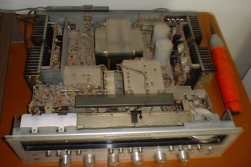
Time for some pics.
I started with this -
Now it looks like this!
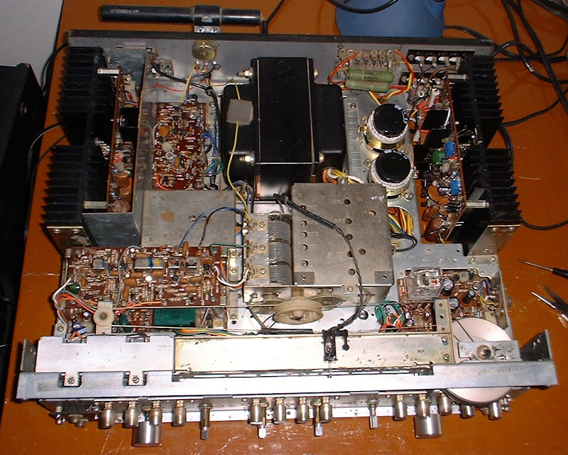

More pics here ....
https://picasaweb.google.com/prasadb/Marantz2270#
I started with this -
Now it looks like this!
More pics here ....
https://picasaweb.google.com/prasadb/Marantz2270#
PooPoo
Active Member
Will MJE15032G and MJE15033G work for the replacement if the H758 (2SC680) and H759 (2SA566)?Firstly, apologies for the long delay since the last post, but life
had other demands on my time, and I could only to get to work
on the 2270 the last few days.
I think I finally have it licked. Both channels are working fine now,
and I can set the bias correctly now. A longish report -
1) The resistors at R769/R770 should be 680 ohms as per the
service manual, but both channels had 380 ohms at these locations.
Replaced them with 680ohms, 1/4W.
2) On both channels, diff pairs H751/H752 (2SA640) replaced by
a pair of 2SA992, matched Hfe of 500 each. The pinout was the
same, so it was an easy replacement.
H753 (2SC945) was replaced on both channels with a BC546
which has a different pinout, but it fits nicely with no bending of pins etc.
3) Current protection circuit - H754/H755 (2SC735) and H766/H767 (2SA562) were replaced with 2N3904, and 2N3906 respectively.
I found that a couple of the old ones were bad (tested with
a AVR transistor tester after removal). Also, one of them was
replaced in a previous repair, so made sense to replace them all, on
both channels.
4) On both channels, H756/H757 (2SA484/2SC484) had been changed
during the previous repair to SK100/SL100s. These
were replaced with 2N3440 at H757 and 2N5416 at H756.
There really are very few TO-39 transistors available, and even
these were not easy to locate locally.
5) The output transistors were unmarked and rusty and suspect.
I changed them to MJ21195G/MJ21196G
Now the left channel worked fine, and the bias could be set correctly.
But the right didn't want to cooperate, and the bias was
still not working.
The only devices left to replace were the TO-66 drivers -
H758 (2SC680) and H759 (2SA566).
I used TO-220 drivers MJE15032/MJE15033. These fit well into the
TO-66 layout and the heat sink can be reused too.
It would be easier to fit TO-220s into the old heat sink,
if the holes for the pins in the old heatsink are drilled out to
a slightly larger size.
There were a couple of zener diodes H764/H765 which are
WZ-071 (7.1V, 0.5W). Considering I had almost rebuilt the whole
board, I replaced them with the nearest match available which
is 7.5V, 0.5W (1N5236).
Thankfully, the right channel worked after all this.
The bias pot is highly sensitive, though. A slight touch and there is
a big change in the bias. Is that normal?
I think it would be worth replacing the original pots with Bourns
multi-turn trimmers to have better control.
Any suggestions for the suitable part number? TIA!
Catrafter noticed that the amp had a pair of 10 ohms, 10W resistors.
Apparently, this is an old repairman's technique used for
debugging - during normal operation, there is little
voltage drop across these resistors (I measured 4 Volts
across them during normal use),
but in case of any short or malfunction, there is a big drop
across these resistors, which hopefully will prevent further damage to
other parts on the amp.
To sum up, it was a lot of work getting this to work properly
and rather frustrating at times, but it was fun too, and I learnt
a great deal in the process. There is a wealth of information in
the old posts on this forum.
Thanks to everyone here, and specifically to ecluser and Catrafter
for their help.
Will MJE15032G and MJE15033G work for the replacement if the H758 (2SC680) and H759 (2SA566)?
Yes, pl see post #25 - I have used the MJE replacements and they work well, but the holes in the TO-66 heatsink
needed to be enlarged to make sure the TO-220 leads do not touch it.
Here's a bad pic showing what I had to do....use your discretion if you want to go this way.
I would heed Catrafter's words above as they come with years of experience.

Do any of these reading vary when you rotate the bias pot?
Why is the right channel's bias asymmetrical?
You did the offset adjustment, right?
Tom
Hey Tom, I'm having a similar problem to quadtech on my right channel, but the symptoms diverge here. When measuring between J754-760 I get 0mV when the pot is full ccw, and as I turn the pot it slowly climbs to around 2mv, then sharply drops back to 0 for the rest of the range. When I measure between J753-755 and J759-761 I measured around 100mv, and both sides respond to changes in R763. I didn't actually notice any distortion, but I'm listening with lower end speakers at the moment so it might just not be audible through them. Any ideas?
catrafter
Marantz Specialist
Serial Number above 3901, right?
It appears that you have NO bias current.
You SHOULD have about +0.6VDC (referenced to chassis ground) on H760 C and about -0.6VDC (referenced to chassis ground) on H760 E, adjustable by R763.
You can measure between the metal cases on the output transistors for about 10mVDC bias voltage, which equates to ≈25mA bias current.
All Hail Ecluser for his excellent analysis of the 2270 power amp. Read the whole thing.
Tom
Yeah, serial number above. I rolled out the scope and decided to look at the outputs, sine wave at 65Hz and I don't see any jumps at the zero crossing, it looks perfect... I'm not blasting the volume though, not sure if that makes a difference. I also checked a square wave, L+R are identical and beautiful. I'll check referenced to ground and see if I can see anything, but it's super weird because everything else seems to check out... Oh, except one thing, what would happen if I connected the power transistors in the wrong sockets? I'll report back in a few minutes with the other voltages. I've read through the analysis a few times, I should add that I just did a full recap and also replaced H760/mounted it on the other heatsink
Oh, probably worth mentioning my replacement H760s are 2N4923G https://www.mouser.com/ProductDetail/ON-Semiconductor/2N4923G?qs=vLkC5FC1VN8b/slVzWxqKg==
It works fine in the other channel though
It works fine in the other channel though
Similar threads
- Replies
- 49
- Views
- 26K