

You are using an out of date browser. It may not display this or other websites correctly.
You should upgrade or use an alternative browser.
You should upgrade or use an alternative browser.
A Field Guide To Fisher Components
- Thread starter TheRed1
- Start date
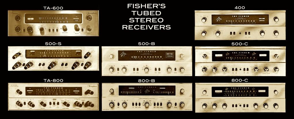
When you do the preamps, remember that the 400-CX has a flat faceplate and oval buttons, the 400-CX2 has the extruded faceplate and round buttons. I think they both say "400-CX" on the front.
Beautiful! I'll take two copies of the wall poster.
OH YEAH!
CHAPTER 1: "That FISHER will cost you an arm and a LEG" OR....how to cost yourself another $200 in parts by plugging it in 1st and THEN after getting nothing or smoke and arcing, asking marginally coherent questions that make absolutely no sense to anyone except someone under 20.
+2 on the POSTER!!!!
LARRY
Red, I just realized that you missed one - the 1800 should be under the 800C. I know it kind of screws up the symmetry, but you could always add the "big numbers" versions to balance things out.
http://www.audiokarma.org/forums/showthread.php?t=314670
http://www.audiokarma.org/forums/showthread.php?t=316021
http://www.audiokarma.org/forums/showthread.php?t=242285
http://www.audiokarma.org/forums/showthread.php?t=314670
http://www.audiokarma.org/forums/showthread.php?t=316021
http://www.audiokarma.org/forums/showthread.php?t=242285
Last edited:
Check out down toward the bottom, just above the X1000 info. Looks like "STUDIO STANDARD" wasn't just a Solid State Moniker.
http://afaudiolab.com/html/fisher_cat_lafayette/index.html
Larry
http://afaudiolab.com/html/fisher_cat_lafayette/index.html
Larry
Bryantenn
Media migration man
I've been the proud owner of the 500-S model. Obtained it from the original owner in 1974! He was our church youth group leader and he gave it to me as a gift because he saw that I was a budding "audiophile" and he had replaced it with a modern Sansui receiver. John Shoaf, was his name. Unfortunately, I've lost contact with him, but it was a great gesture, and over the years, it was dragged to college, then stored for almost 2 decades, and finally, I restored it back in 2007. Now it plays in my study. Sweet sound from the 7189's and the cool look of the brass faceplate still gives me warm fuzzies. Still trying to score an MPX decoder, but I just can't stomach the $$$$ those things go for on the auction sites. Anyway, it's a classic, and I love listening to it on my Tannoys. Aswesome sound.
TheRed1
Console Conservationist
A Field Guide To Fisher Components, Page 2:
Missing from the above are the following X-Amps that I know of:
X-19 and X-190 Allegro Amps
KX-20 Stratokit (?)
KX-90 Stratokit and the X-44 factory wired version
X-100-2
X-100-3 (aka: X-100-A?) 7189 tubes? Possibly an export verion of ____ ?
X-101-ST (The console version was known as the X-1000 but was different from the one pictured above.)
Are there any more?
If anyone has either a decent photo from life or a scan from advertising of any of the omitted X-amps, perhaps they might care to submit it in order to expand the Field Guide?
The X Files:
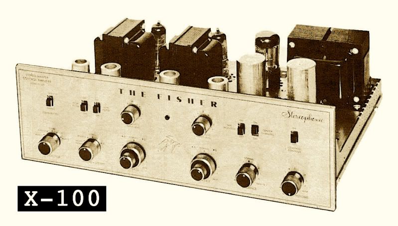
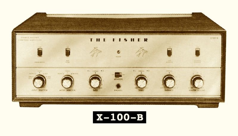
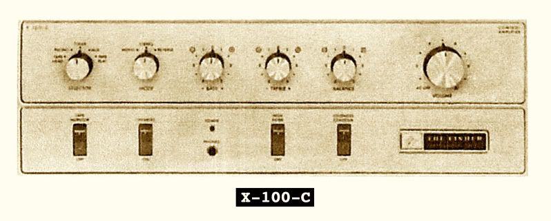
Fisher's Stereo Integrated Tube Amps
X-100, circa 1960 - EL84/36 watts (IHF)
X-100-B, circa 1963 - 7868/50 watts (IHF)
X-100-C, circa 1965 - 7868/50 watts (IHF)
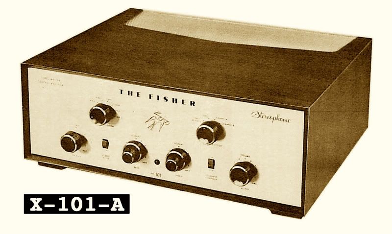
X-101-A, circa 1959 - EL84/40 watts (IHF)
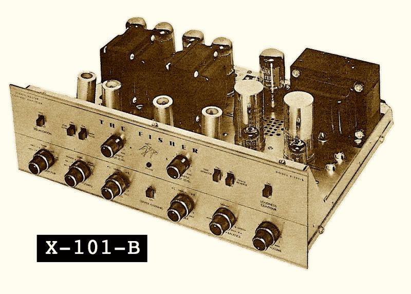
X-101-B, circa 1962 - 7591/60 watts (IHF)
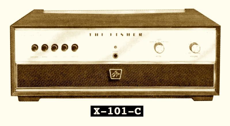
X-101-C, circa 1963 - 7591/60 watts (IHF)
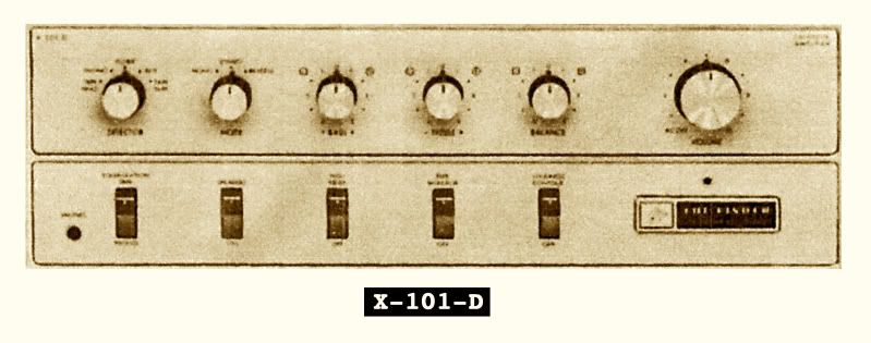
X-101-D, circa 1965 - 7591/ 66 watts (IHF)
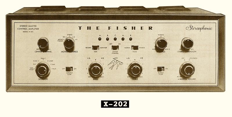
X-202, circa 1960 - 7189/50 watts (IHF)
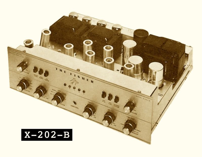
X-202-B, circa 1962 - 7591/ 80 watts (IHF)
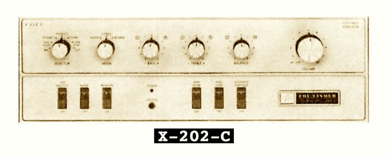
X-202-C, circa 1965 - 7591/84 watts (IHF)
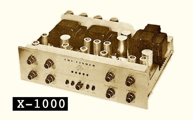
X-1000, circa 1962 - EL34/110 watts (IHF)
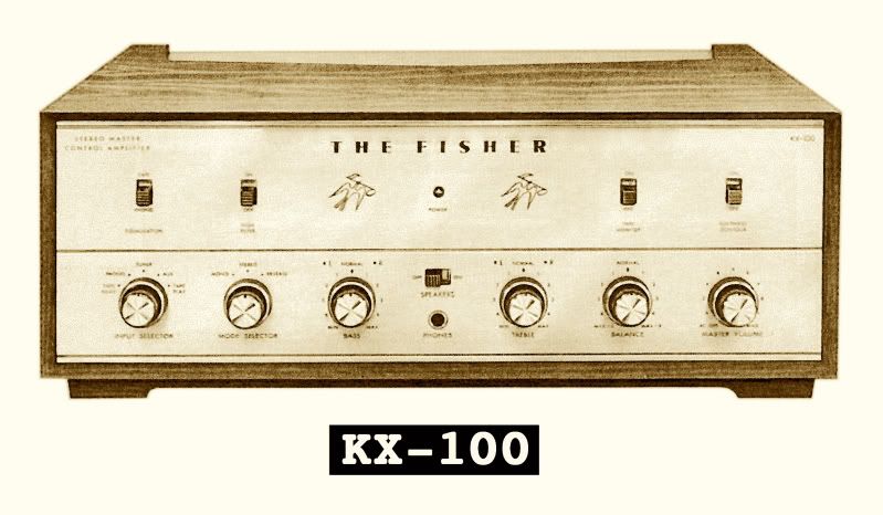
KX-100, circa 1963 - 7868/50 watts (IHF)
KX-200, circa 1963 - 7591/80 watts (IHF)
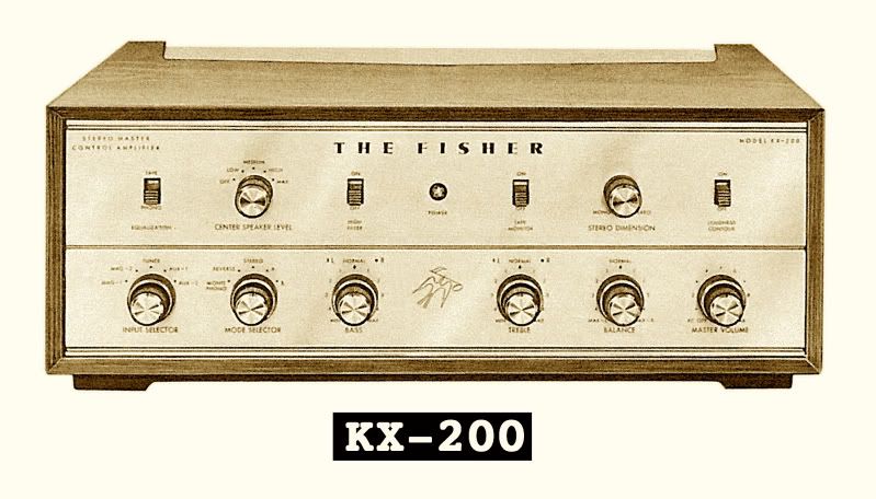
(Factory Wired Version: X-200)
Fisher's Stereo Integrated Tube Amps
X-100, circa 1960 - EL84/36 watts (IHF)
X-100-B, circa 1963 - 7868/50 watts (IHF)
X-100-C, circa 1965 - 7868/50 watts (IHF)
X-101-A, circa 1959 - EL84/40 watts (IHF)
X-101-B, circa 1962 - 7591/60 watts (IHF)
X-101-C, circa 1963 - 7591/60 watts (IHF)
X-101-D, circa 1965 - 7591/ 66 watts (IHF)
X-202, circa 1960 - 7189/50 watts (IHF)
X-202-B, circa 1962 - 7591/ 80 watts (IHF)
X-202-C, circa 1965 - 7591/84 watts (IHF)
X-1000, circa 1962 - EL34/110 watts (IHF)
KX-100, circa 1963 - 7868/50 watts (IHF)
KX-200, circa 1963 - 7591/80 watts (IHF)
(Factory Wired Version: X-200)
Missing from the above are the following X-Amps that I know of:
X-19 and X-190 Allegro Amps
KX-20 Stratokit (?)
KX-90 Stratokit and the X-44 factory wired version
X-100-2
X-100-3 (aka: X-100-A?) 7189 tubes? Possibly an export verion of ____ ?
X-101-ST (The console version was known as the X-1000 but was different from the one pictured above.)
Are there any more?
If anyone has either a decent photo from life or a scan from advertising of any of the omitted X-amps, perhaps they might care to submit it in order to expand the Field Guide?
***Please feel free to point out any errors, add further information or expand the Field Guide into other component groupings.***
I am sorry but there are no posters available at this time. The graphics card on my ancient eMac would surely melt if I were to attempt anything remotely approaching poster-quality resolution. If there are any AK members with the capability of producing such a poster, I think it would make an excellent fund raising item for AudioKarma. I have used grainy old ads for the majority of my source images which would probably look terrible blown up. Higher-res photo submissions from members with nice looking examples would be the way to go. I can offer up my TA-600 and 800-C.
Last edited:
Fisher 150 Receiver Temp Compensating Diodes
I am repairing a Fisher 150 receiver and have encountered a problem with the
temperature compensating diode module on the heat sink in one channel. It is
a gray plastic device with two series connected diodes inside and one is
fried to be a 120 ohm resistor! The Fisher part number is SIT-50-B843-4.
I'll include a couple of pictures of the device. It is approximately 1-3/4"
wide, 1 3/8" long, and 7/16" tall with 4-leads protruding with two being
connected together to make the series circuit. Does anyone happen to have this available or know the diode temperature characteristics? My first thought is to drill out the diodes and replace them with 1N4148's and then re-pot it
with J-B Weld and re-attach it as if it were an original - with the repair
on the "unseen" side! What do you think? Ideas welcome!
Please do not reply to this post here. I have asked the poster to start a new thread on this topic, and then this post will be deleted. Post any replies in the new thread. Thanks.