AD797 Phono Stage Build and Help Desk Thread

Before getting too concerned about matching these bypass caps closely, remember that they are being installed in parallel to electrolytic caps and the tolerance range on those is going to be considerably greater than the 100nF value of the caps you are concerned about matching.

Well, you called that right. The matching for the Elna 10uf 35V caps range from 9.463uf to 9.715uf. The range for the Elna 10uf 50V ranges from 9.364 to 9.583. I bought at least twice as many as I thought I'd need but can't come up with close enough quantities for my dual mono build. Are there caps that have closer tolerances than 20%?
 
There may be some available but I've not personally run across any electrolytics with tighter tolerance. I'm not sure that it is even possible from a bulk manufacturing perspective. I don't think you should be too concerned here. Precision isn't a great benefit in this application and there isn't a great return for all the effort a person could put into trying to match capacitance closely. Save your efforts for the capacitors and resistors of the RIAA filter where you have a much greater chance of hearing the benefits of matching.

I'm curious what you mean when you call it a "dual mono" build. Are you referring to the power supply?
 
I'm building one channel on one board and one on another. I has a dual mono power supply as well. I built that for a RJM Phonoclone.
So what exactly makes up the RIAA filter?
I'd spend more time and money there if I knew. .
Thanks
 
R6 (200K) and R8(16K) are RIAA resistors. Values are correct but numbers come from a schematic I took from the board and may or may not have transcribed correctly.

I used Polystyrene capacitors in my build, matched within 10pF, and the suggested Dale resistors matched within 1/4%. Given all the other variables at play, I suspect I wouldn't be able to differentiate any closer matching by listening.

I'd be interested to hear how your approach would compare to the conventional build. I've a similar project going with the LME circuit that is the basis for the CNC. I've built a 2 X dual opamp version with no supply bypassing at the opamps, and have a 2 X dual opamp version with full-on bypassing as well as a 4 X single opamp version under construction. All will use OPA627 chips, on browndogs where required. I'm betting it's going to be tough to differentiate which is which once I start comparing but I'm hoping to be surprised.

So just the two sets of resistors R6 & R8 are in the RIAA filter? No caps? I'm really ignorant regarding this. I thought there would be more to the filter or to match closely. You mentioned polystyrene caps. Which ones are important?
Thanks for the information!
 
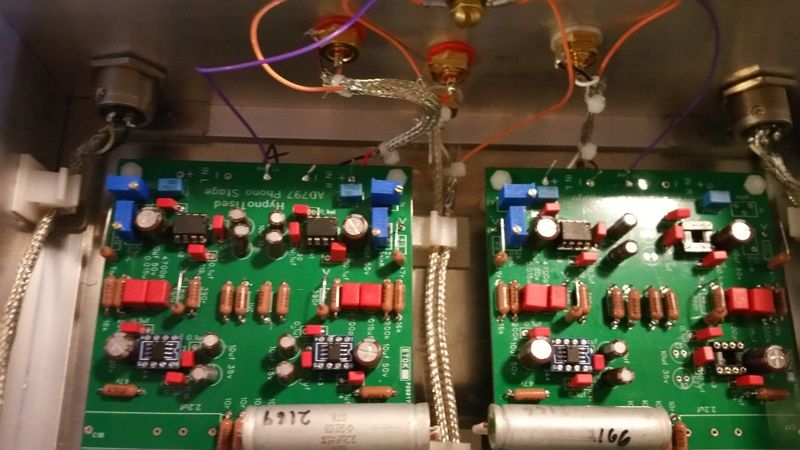
The 4.7nF and 15nF film caps are the other components in the filter. I used polystyrene as a substitute for the polypropylene caps you have likely acquired if you followed the suggested bill of materials. The RIAA resistors and caps install near each other on the board. There is a wealth of good information and advice about the project in this thread. It is worth the time to go through the posts, the important ones stand out, and doing so will greatly help your understanding of what you are building.
 
Thanks. I've read this thread multiple times forward and backwards but never picked up what exactly is in the RIAA Filter. Thanks for your help!
 
I went over this thread and other material many times until the pieces started to fit together in a way that made sense. A little knowledge is a wonderful thing when you have to start troubleshooting and so far, every build has required that. Good luck with your project.
 
Sorry, it's audjade_chn; I got the 797 op amps from him as well and some 4.7uF silmics. He sells a variety of parts aimed at the diy upgrade market and from my experience and all I've read, he is reliable. I've tried a variety of other China based sellers of op amps and only these two have shipped genuine parts.
The 627 chips do really well with the 797 chips in this preamp. I haven't used the 49990 but I have tried the 49710 and find the 627 to be notably better. I'll also mention that this preamp surprised me with how good it is. In my experience, most diy RIAA projects are pretty good; this one is head and shoulders above that level.

I can confirm that the OPA627BPs do sound absolutely sublime in this preamp. For my ears and taste the OPA627BPS is the best IC opamp in this preamp, though, I have replaced them with SparkosLab SS3601 discrete ones that are even better. I can full heartedly recoment the Sparkos ones in the second stage. The ones in the first stage are AD797BRZs. No more upgrade for me.This preamp is among the best I've heard so far. You have to spend thousands in USD to better it.
My Hana SL sings beautifully in the 9CC Evolution arm of the Pro-Ject 6 PersPex turntable feeding the Jolida Fusion 3502 integrated with KT150 tubes driving a pair of KEF R500s. I do enjoy my records every day.
The only upgrade itch that tickles in me is to try a tube buffer after this preamp though it might not be needed since I have tube integrated. I should stop being an engineer and just enjoy music to its fullest.
 
I'm running mine with 9v batteries still as I can't seem to get my ps going with a wall wart. Wondering if these will eat the life out of the 9v's.
 
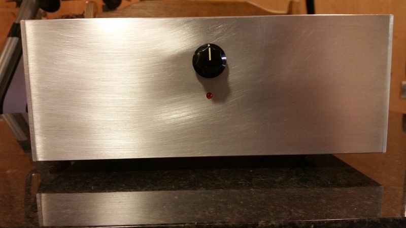
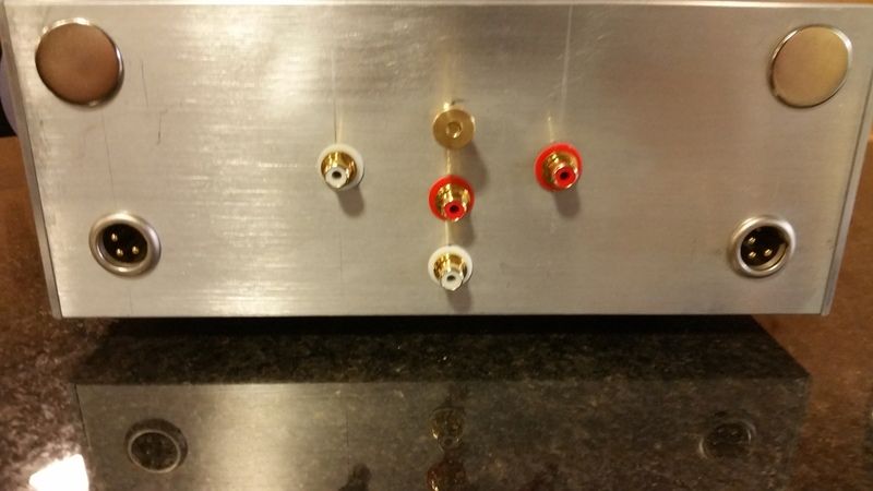
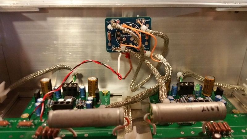
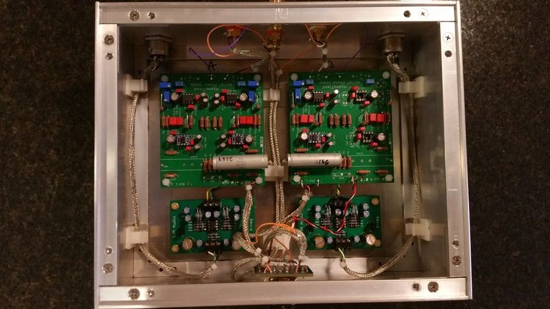
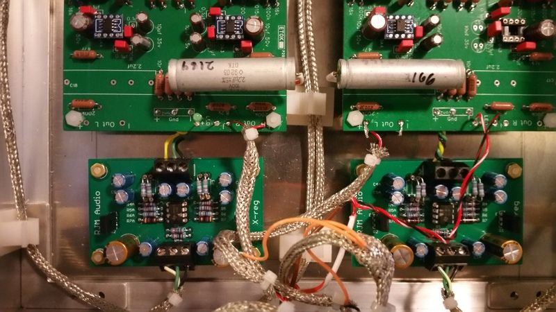
Well the dual mono set-up lives and sounds wonderful with a couple of sides under it's belt. Quiet as all until a tiny bit of tube rush at the highest volume settings. Great spread of instruments and very delicate on top with very nice deep bass. The horizontal RCAs are for the inputs so as to keep the wires as short as possible. The vertical ones are for the outputs. I attempted to avoid crossing the I's and O's. Switch on the front is stereo-mute-mono. I matched up the two boards components as closely as I could with my cheap Ebay tester. IDK if it was worth it but I'm pretty satisfied.

20170211_090152_1486823241872_zpskghs1jje.jpg


20170211_090207_1486823241741_zpsjfrvdhk8.jpg


20170211_090215_1486823241456_zpsf6ohfrpo.jpg


20170211_090132_1486823241975_zpsvukqweda.jpg


20170211_090106_1486823242080-2_zpscizgqokz.jpg


20170211_090100_1486823242184_zpssa2c8cdu.jpg
 
Wood cases? I like wood cases as well but after completing my first preamp project using a wooden case I got a strong ground hum. I tested by wrapping aluminum foil loosely around the case and attaching the foil to ground and the hum diminished considerably. I worked out a method to shield the box using sheet aluminum and did that for all subsequent projects.x

View attachment 785534

I prefer using connectors rather than soldering the hookups, at least for the preliminary testing stages. It allows much easier disassembly if you have a problem that needs fixing or want to change capacitor types. I'd strongly recommend using styrene capacitors for the RIAA and loading capacitors and matching them and the resistors very tightly. Mouser carries them and they are quite inexpensive. Replacing the twisted pair hookup wiring with shielded twisted pair with shield grounded to source end also provided substantial hum reduction.

What connectors are you using for hooking up the inputs/output to the board? I cannot seem to locate a similar connector.
Thanks
 
Strip the plastic housing off the connectors you used on the power supply boards and you will end up with three pieces that are very similar to what I used. The connectors I normally use are quite similar but at 5mm pitch, didn't fit the hole spacing on the boards. It was virtually impossible to find connectors with the appropriate pitch so I improvised.
 
working on my 797 today and it proceeded to drop a channel. 3 hrs later all it took was to reflow the rt channel input rca. That's what I get for thinking the rca needed snugging up. If it ain't broken don't fix it.
 
Back
Top Bottom