http://www.hifiengine.com/hfe_downloads/index.php?agi/agi_511a_ah_schematics_low_res.pdf
By not getting any sound out, meaning already hooked up to a known good amp, and when you put a known good source signal into say the Tuner or Aux input, and select that source via the corresponding selector button you get no output from the preamp to the amp via the volume control? I assume none of the Tape or Tape monitor or Dubbing switches or other input source switches are pushed in.
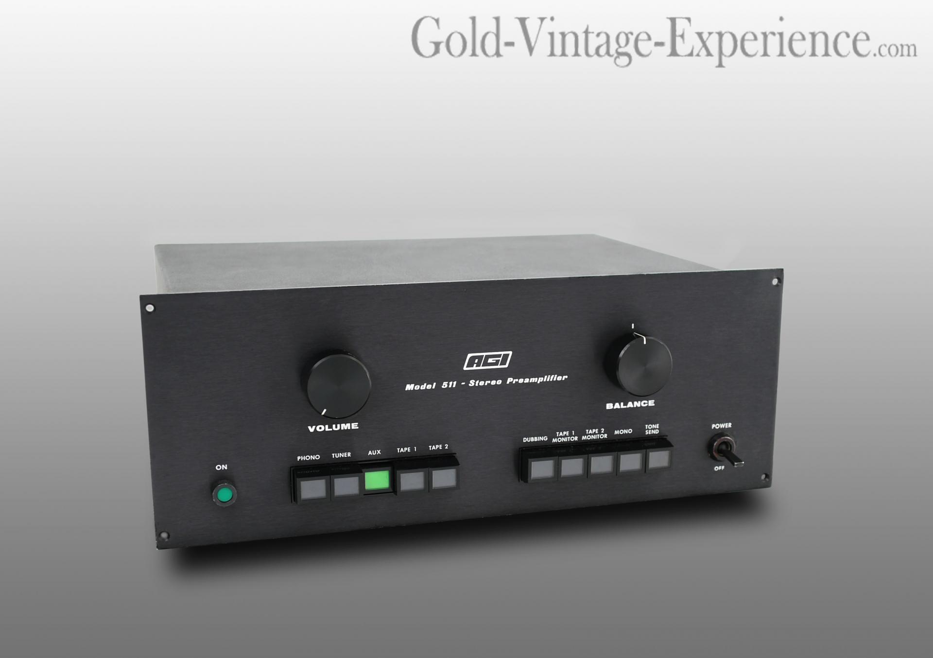
Can you post some pics of the preamp, including the front and back panels, and then the top removed showing the circuit board? Then we can see if anyone has been in there before you.
British back panel
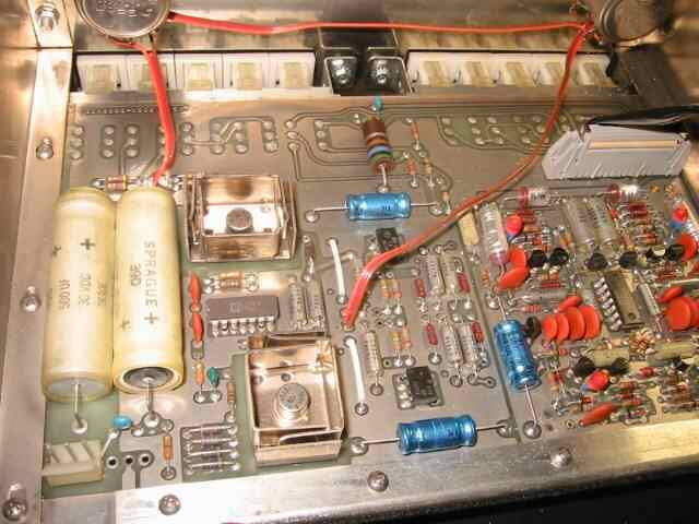
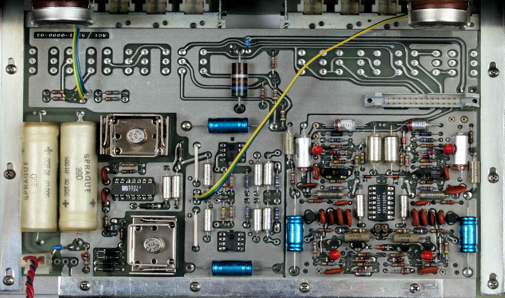
Here's some pics of what I think is the original looking board:
This ribbon cable takes all the input signals from a PC board where all the input RCA are solder to and passes them into the main board. My understanding is that board and its connections to the ribbon cable and the RCA plugs they used can become intermittent or troublesome.
Never worked on it but here's a basic circuit analysis - its circa 1976 or so, and the design reflects that era. The main board is well laid out with a double sided board, ground planes and clean tidy design, components were good for the day, note the use of axial electrolytic caps, a lot of small ceramic or possibly tantalum caps (little orange disc guys)
1. page 3 of the schematic - The power supply is a basic transformer producing 18VAC feeding a discrete full wave rectifier bridge and two 500uf smoothing capacitors, one each for the + and - legs. The rectified DC is then passed to a pair of 3.5W pass transistors which are controlled by a Silicon General SG4501 dual (+ and -) voltage regulator chip. That whole section ensures you get a solid referenced +/- 15V output, so at C74+ referenced to ground should be +15VDC, similarly at C76(-) referenced ground should be -15VDC. That is your first step, to ensure the power supply and regulators are working properly. If not, likely you need to recap the power supply, and check the diodes, then the resistors, then the transistors, and if nothing else, the regulator chip.
2. page 2 of the schematic - Shows the input board connections, the selector switching scheme, and the line level preamp section - everything goes through the line level amplifier stage consisting of two LF357 fast op amps (but obsolete by today's standards) and finally through two DC blocking coupling caps at the output (50uf non-polar electrolytics most likely). The LF357's are the two black rectangular 8 pin IC chips in the middle of the board, and likely the two blue axial caps are the output blocking caps.
3. Page 1 of the schematic - Fully devoted to the phono preamp section - Left channel on the schematic left, right channel on the schematic right.
Input from the cartridge is sent to 1/2 of a uA749 dual op-amp where initial parts of the RIAA eq is started, then signal passed to two stages of push-pull symmetrical transistor amp stages where additional RIAA eq and gain are added, leading to the phono outputs in the center of the schematic which then pass to the Phono selector switch and then the line amp.
So the basic troubleshooting would be to check PS voltages, then DeOxit clean all input RCA's (gently), then pushbutton switches, the ribbon cable connection to the board, making sure its firmly seated in the connector base, and possibly try to clean the volume and balance pot. However, the pots look like the very good and common Bourns large sealed pots, so if cannot get a place to spray, then rotate them 20-30 times to try to knock off any oxidation off the internal contacts.
Then use various signal inputs (other than phono) to see if ANY of them work - if at least one does, then the preamp section works, and its an input connection problem. If all the sources still don't work, then you'll need to dig further.