Amp layout?

Tube gear rarely uses a lot of shielded wire. I don't honestly know why, but I guess the engineers decided it wasn't needed most of the time. I do have Stromberg-Carlson gear that is loaded with it though. A lot of things get by with nothing more than a grounded lead twisted around the signal wire for shielding and it works out fine in most cases. The metal chassis itself serves as a shield as well. You'd figure with all the high impedance circuits these things would pick up noise like crazy but it just doesn't seem to be the case. Seems like it would make good sense for longer runs from input jacks, but it may not be needed for short internal runs.


One thing I can think of is the way the tube circuit works. The voltage signal in the tube circuit before the output transformer is very high amplitude. The output transformer has a voltage divide ratio like 30:1 or more. So whatever the voltage noise induced into the tube circuit is reduced by the divider ratio of the output transformer. So the effect is a lot less.

Another finer point is noise coupling is like a loop antenna effect like the UHF antenna. The radiation is proportion to the loop area AND the current around the loop. Let's just say the loop area is the same between the tube circuit and the SS circuit. Tube circuit is high voltage swing ( doesn't matter in this context) but low current ( as circuit impedance is high). The magnetic field generates is small as the current is low. So the radiation is weak. In SS circuit, current is high even though the voltage swing is low. BUT loop radiation is ONLY proportional to the loop current ( assume the area is the same). So the radiation from the SS circuit is a lot stronger. So tube circuit is a lot more immure to radiation it this sense........BUT...........

It's not all good news for tube circuits. You have magnetic coupling between the power transformer to output transformer that you don't have in SS amp. I have issue with my kit amp and proven to be crosstalk between the power and output transformer. Once you have the position of the two transformer fixed and if you have problem. You are stuck. So you have a different set of problem with tube amps. This kind of coupling is NOT going to be fixed by shielding. You need thick metal for shielding. In EM theory, it's the EM wave penetration through the material that's the key. The lower the frequency, the longer the wavelength, the thicker the metal has to be to block the radiation. So a normal shield or ground plane on the pcb is not going to do anything. You need a thick metal box.
 
Tube gear rarely uses a lot of shielded wire. I don't honestly know why, but I guess the engineers decided it wasn't needed most of the time. I do have Stromberg-Carlson gear that is loaded with it though. A lot of things get by with nothing more than a grounded lead twisted around the signal wire for shielding and it works out fine in most cases. The metal chassis itself serves as a shield as well. You'd figure with all the high impedance circuits these things would pick up noise like crazy but it just doesn't seem to be the case. Seems like it would make good sense for longer runs from input jacks, but it may not be needed for short internal runs.

Much of the small shielded wire has (relatively) high capacitance. Given some (most?) tube circuits are high impedance doesn't that tend to cause additional concerns for stability and or frequency response?
 
I forgot one thing, since tube circuit is much higher impedance, capacitor coupling between signal wires is a lot more serious problem. BUT the good news is tube circuit is usually very big, components are huge comparing to SS circuit. So if you layout out the components carefully like in this thread, signal wires is a lot farther away from each other and capacitor coupling is not an issue.

I remember when I was designing my guitar amp, I started out with a certain circuit and layout the components accordingly. Then as I work on the circuit, I added more stuffs and I have to jumper the new circuits into the existing layout. Pretty soon, the wires of the signal path started crossing. I got the amp working, but the sound was always kind of strange. But it's good enough. So I took the new circuit and did the final layout and smooth out the signal path to get no crossing. The final amp sounded quite different in a much better way. Getting rid of the cross signal path really helps.

So the way Whoaru99 first design the placement is VERY IMPORTANT to get the signal flow defined to avoid cross path.
 
Heh...I'm still hoping for some good suggestions on how to mount stacked film caps in that space between the power tubes and choke. :)

A piece of pref board, maybe, (yeah, yeah...I know, a custom circuit board) with an insulating sheet underneath and spaced up on some nylon stand offs? I could run the wires into the chassis through a couple of small bushed holes rather than doing any sort of large cutouts. Remember, the stacked films I'm eyeballing are good size, 57mm L x 35mm W x 50mm H. If I can't figure out a good way to mount them I might have to downgrade to more salt shakers. ;)
 
Tube gear rarely uses a lot of shielded wire. I don't honestly know why, but I guess the engineers decided it wasn't needed most of the time. I do have Stromberg-Carlson gear that is loaded with it though. A lot of things get by with nothing more than a grounded lead twisted around the signal wire for shielding and it works out fine in most cases. The metal chassis itself serves as a shield as well. You'd figure with all the high impedance circuits these things would pick up noise like crazy but it just doesn't seem to be the case. Seems like it would make good sense for longer runs from input jacks, but it may not be needed for short internal runs.
This is not true of the Fisher X202C that i am rebuilding now and it has lots of "shielded" cable throughout for the preamp functions. The same is true for the Sansui AU70 that i just rebuilt was also full of the "shielded cable. The shield was not very complete in that it was mostly a single layer of fine wire wound around the center conductor. So, for the preamp section shielded signal wire was used. The Fisher also went an extra step and put a shield around the AC wire that runs from the AC input at the back of the chassis to the AC switch on the front panel. So, there must have been some AC noise intruding for them to do this.
 
What is the big film caps for? I have no feel what you are talking yet. A picture would be nice.

The power supply is, basically, CLCRC configuration. Thinking at present is to use film for the first C and last C. The salt shakers are the C in the middle.
 
At this point a schematic would be helpful. Usually for the last cap of the CLCRC I tend to have it close to the circuit to minimize the distance between the cap and the circuit. But where you put the ground for the cap is even more important to avoid ground loop. I would first draw out how you going to connect the ground for the filter caps and the circuit.
 
where you put the ground for the cap is even more important to avoid ground loop.


This can be very true. I prefer the term return because it is about how the power supply, audio signal and or noise gets home. This is what dictates the correct return point.

Sometimes this can make a lot of difference, other times not so much, but it is not unusual to find someone chasing an issue on the high side of a circuit and ignoring the return path.
 
Agree. I think now that the placement is good, next step is to get into a little more detail and nail down the return/ground of the major components. Really, from my experience, the power connection is not nearly as critical as the return. Where one put the return of the input stage and output stage is of utmost important. I once help troubleshoot the hum issue of a DIY Fender amp and down to the return of a tube closer to the input chain was put on the wrong star ground of the later stage. Move that wire and the amp is quiet.
 
The thought is to have only a single point return connection to the chassis. Then, either a star ground or one heavy buss bar as the return to that single point. I've done both ways in the past.This layout I think is more conducive to star ground.

Considering there is no plan to use the chassis for return, would one want to locate the ground point centrally to minimize length of any given return?

This is sorta what I'm envisioning for the B+ side.

KT88PSEPS1.png
 
Last edited:
^^^
That said, I'm beginning to feel like I've gone off the deep end on capacitance. I'm going to review all that again. I think if I can keep the plate supply ripple to 10-12mV I'm probably good for my use. That's less than 1mV at the speaker considering OPT turns ratio of about 18:1.
 
I think this is a good and conservative layout, which is unlikely to create issues for you. I especially support your decision to make it bigger than necessary, it's a good idea from the perspective of both cooling and hum reduction.

One thing you may want to do is also lay out the underside, where the terminal strips will go, etc, to avoid a rat's nest from forming.
 
Mount the caps up top? A trany cover would hide them nicely and leave plenty of room underneath. :dunno:
 
In regard to capacitor ripple, if I have reasonably modeled the PS and load (and believe I have) with LT Spice showing 286mA RMS on the first capacitor, a capacitor with rating 610mA RMS should be fine, eh?
 
That 6EJ7 sounded familiar. I had to look up what it is, then I remembered where I'd seen it before.. My Zenith 16" color TV used a 3EJ7 as the chroma oscillator. When it got weak, it would stop oscillating and the picture would go black and white. Does this tube have especially good linearity?
 
Am going to stick with cathode bias at present.

I could fill a lot of that area if I didn't hide the three stacked film caps underneath. Each of those three caps is 58mm L x 35mm W x 50mm H. So the lot of them would take up some real estate.

However, I'm not seeing a clear way to cleanly mount them on top that also looks half decent. Any ideas?

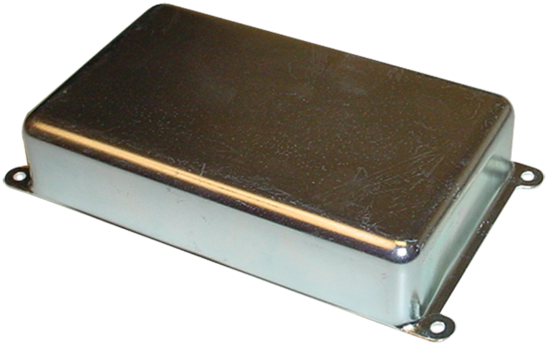
An actual Fender cap cover? May not be what you are looking for,but they are available in different sizes and usually for small money.Great for keeping things hidden on top of a chassis.Zinc plated steel,but they paint up nice.Just a thought.

p-h710.png
 
Appreciate that.

I've done more playing with capacitor and choke values in LT Spice and have come up with (about) plan D. LOL. The PS won't be quite as stiff as the previous beastly plan but I believe the ripple is still sufficiently low, at lower cost (although that is not paramount) and easier assembly.

The way it's headed now is to use four electrolytic caps, all 35mm dia, so I can mount them vertically through the top, using standard capacitor clamps on the underside.
 
The thought is to have only a single point return connection to the chassis. Then, either a star ground or one heavy buss bar as the return to that single point. I've done both ways in the past.This layout I think is more conducive to star ground.

Considering there is no plan to use the chassis for return, would one want to locate the ground point centrally to minimize length of any given return?

This is sorta what I'm envisioning for the B+ side.

View attachment 1035182
I think at this point, it is more important for you to draw a proposed grounding point/scheme like this. The power is really not that critical once you have the placement. What you have here is very reasonable. I want to see how you put the ground/return.

From experience with tube guitar amp, I don't create the grounding with wires, I use the chassis, BUT before people jump on me, I want to explain a little.

I worked with system grounding and signal integrity. Even though in audio frequency( slow), the ground current do choose path, it's not as if the current is all over the place. What I meant is if you have the ground of the salt shaker cap C2-1 screwed onto the chassis close to the grounding of the cathodes of the two KT-88 power tubes( I assume grid bias). The main current will flow in the chassis between the two grounding point as mention, it will not going all direction to get from one point to the other. Of cause the best is you screw the return of the salt shaker cap to the same point as the cathodes of the power tube.

Then the driver tube can have the cathode circuit screw onto the chassis close to the driver tube ( which is away from the power tube), the return of C3-1 screw onto the grounding screw of the driver tube. This way, the two ground current of the power and driver tubes do not cross path at all.

I use this philosophy when I build my guitar amps. My guitar amps are all high gain, channel switching type with very high gain through the signal path. I have no grounding issue, no hum. Main thing is the hiss from the thermal noise and.....of cause, from the guitar pickup if I stand in the wrong position ( even with hum bucking pickups). I did not measure the noise specifically, but just by the ears. But the gain of the guitar amps are so so so much higher than stereo power amp, if I don't have problem with hum, you shouldn't.

JMHO

So just draw out the ground points in the picture. I am ok if you insist in using ground wires instead of the chassis. It's just an opinion from my experience.

BTW, that's how those famous Fender Black Face and Silver Face guitar amps do their grounding. Their circuit is progressive from left to right, they just ground all the cathode of those preamp tube along the chassis on a heavy bus bar. There is no one point ground or star ground, just progressively from left to right ( the power tube on the right side). Heavy current from the power tubes is not going to travel to the right side where the preamp tubes are and cause interference. Current do choose the path of least resistance, the lowest resistance is the straight line from point A to point B.
 
Last edited:
Back
Top Bottom