Another Sansui AU20000

Kale

Super Member
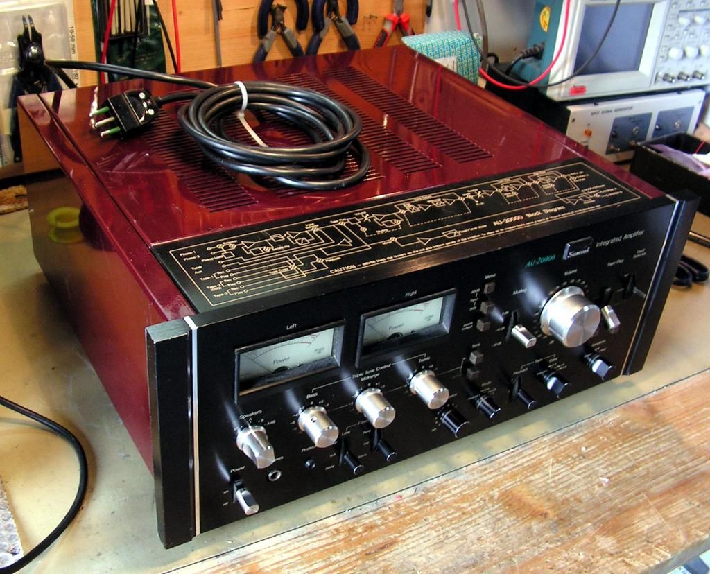
Another big Sansui on my bench… Sansui AU20000!
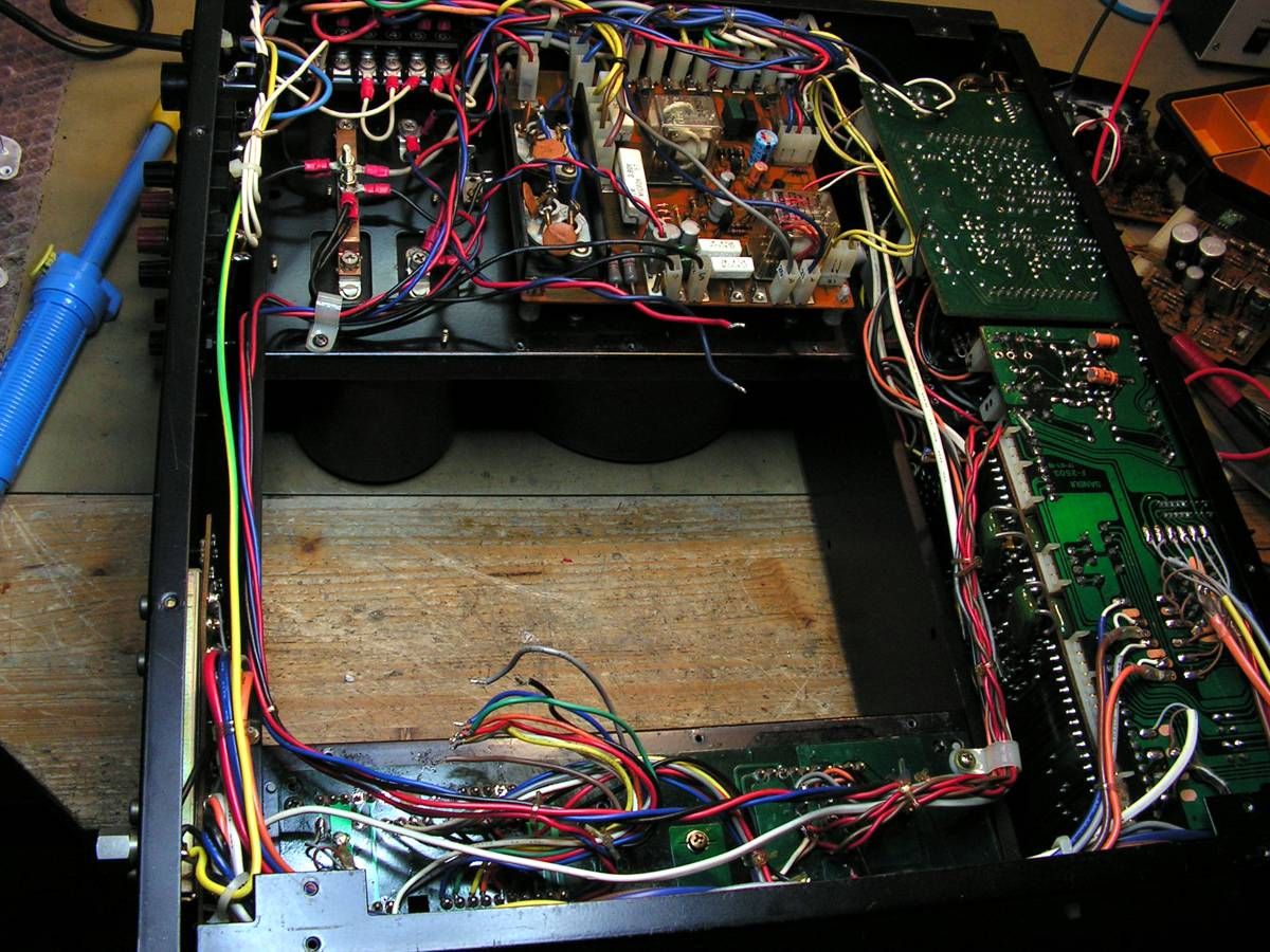
Amplifier has some issues, and someone tried to fix it in the past… but first some pictures how I got it…


PICT2700_zpss6mlzmra.jpg


PICT2701_zpsrakgcsmf.jpg


PICT2702_zpshkbacig1.jpg


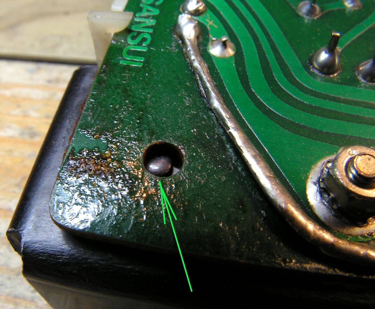
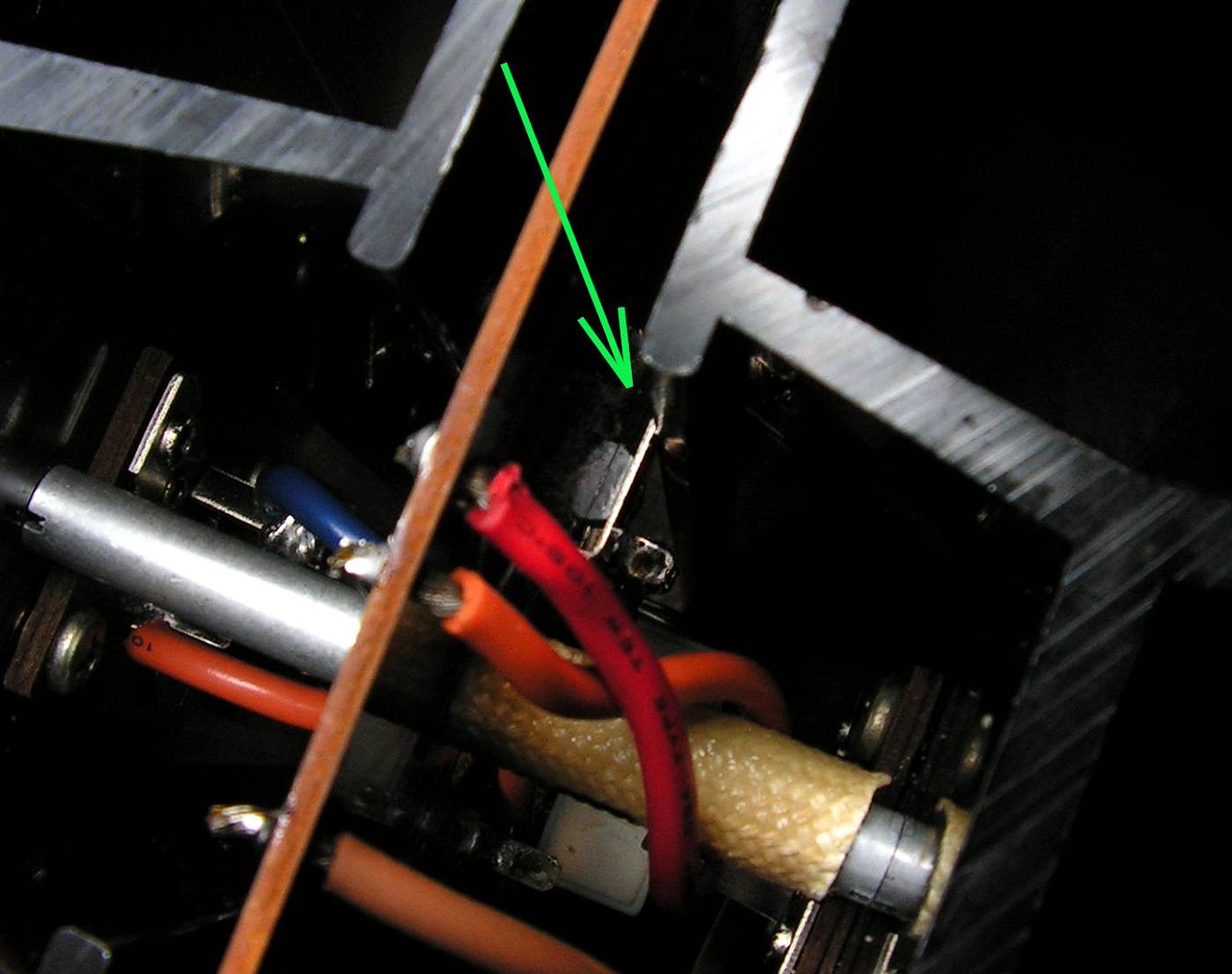
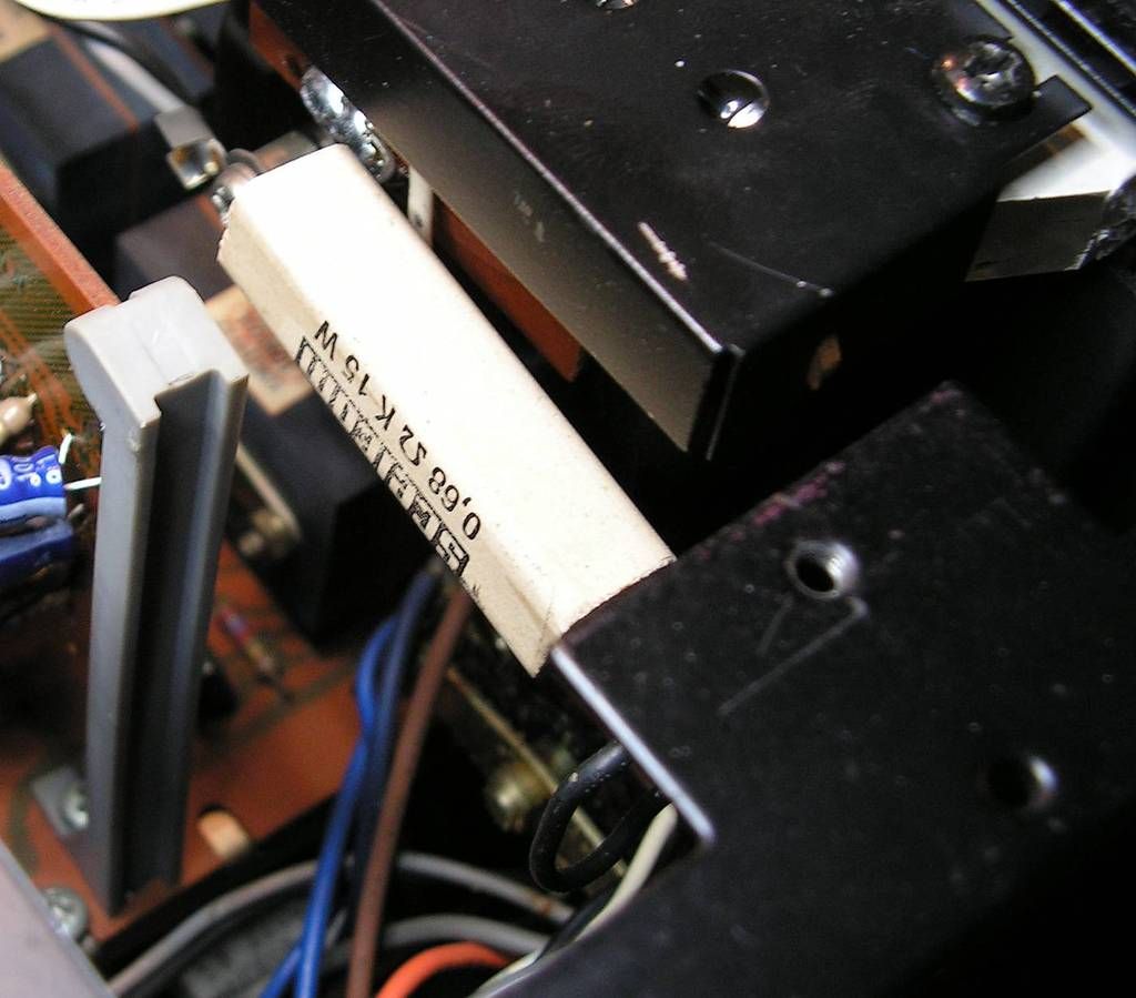
First what I noticed is this ceramic power resistor connected to the power meters (?!)… I will see about that later….

PICT2705_zpsbok86737.jpg


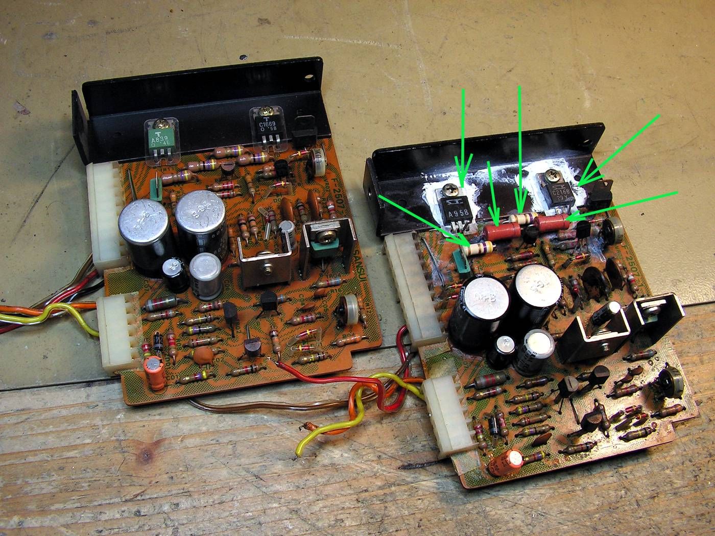
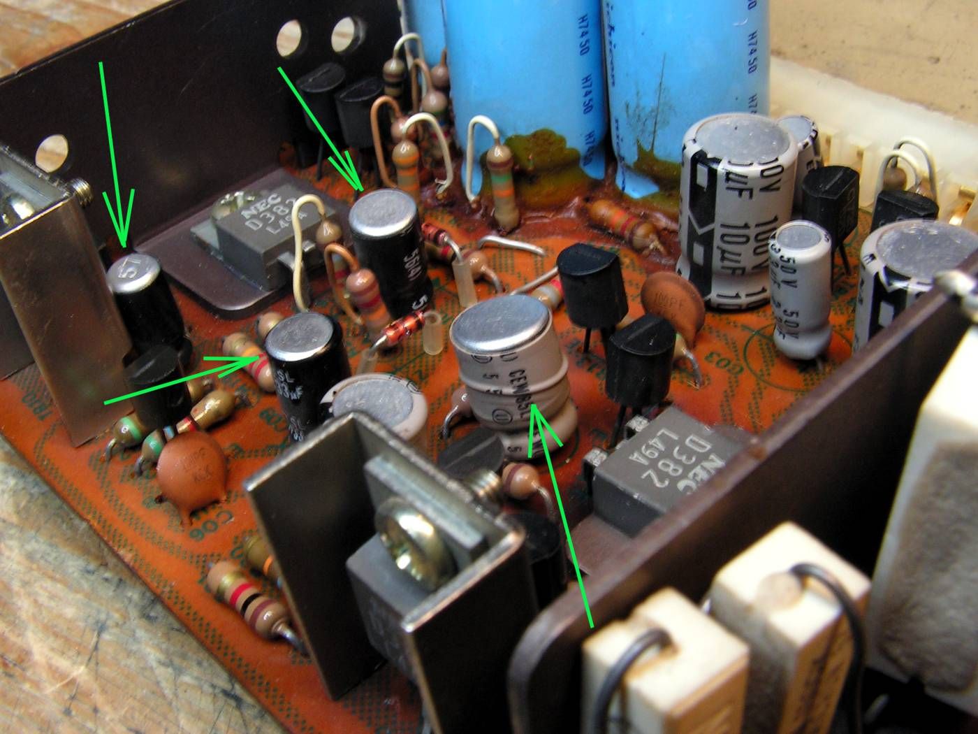
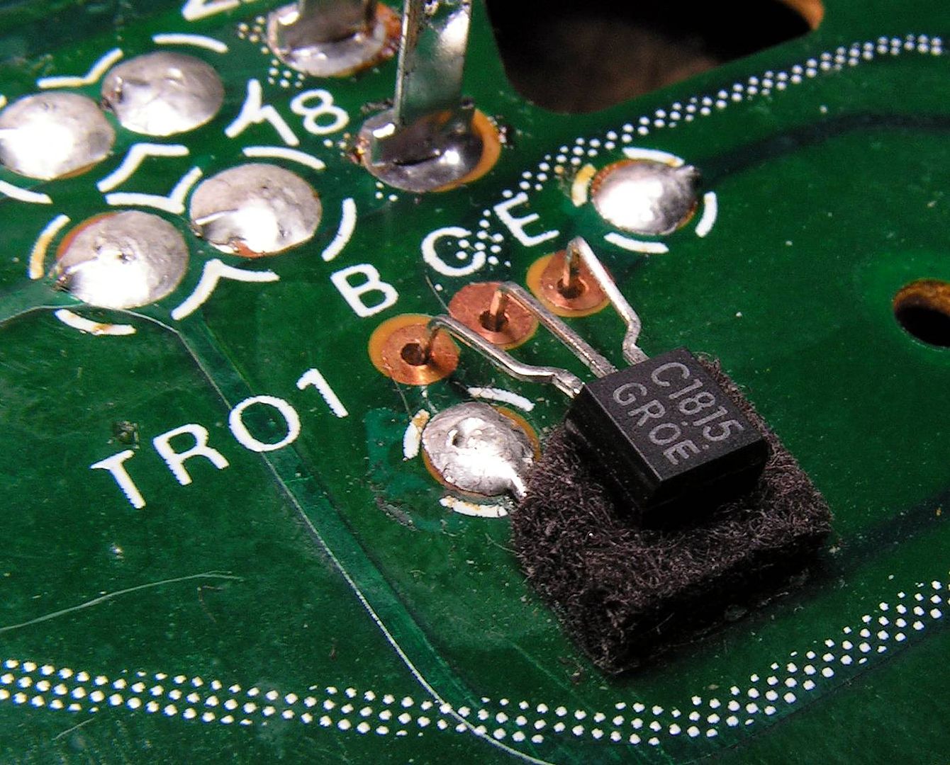
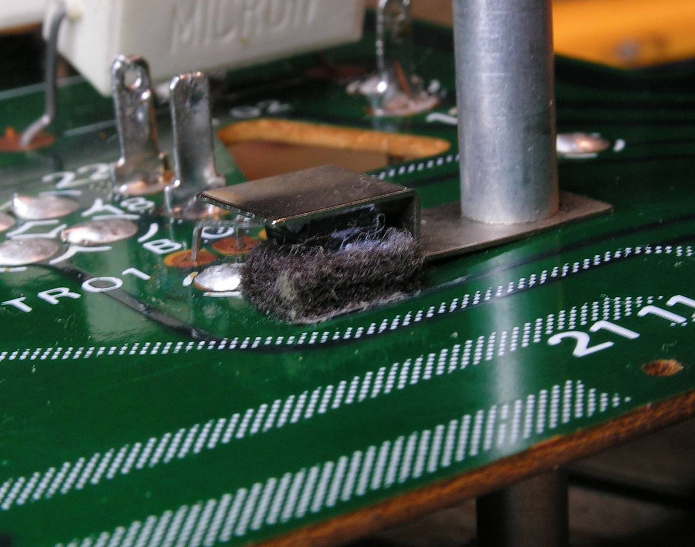
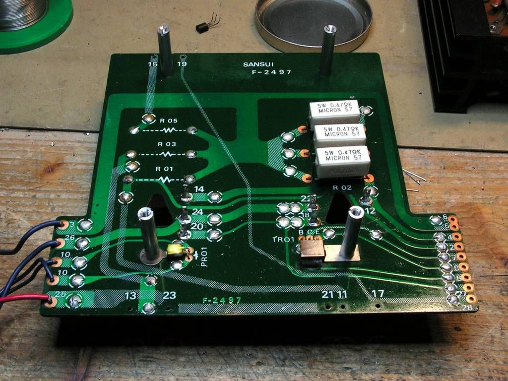
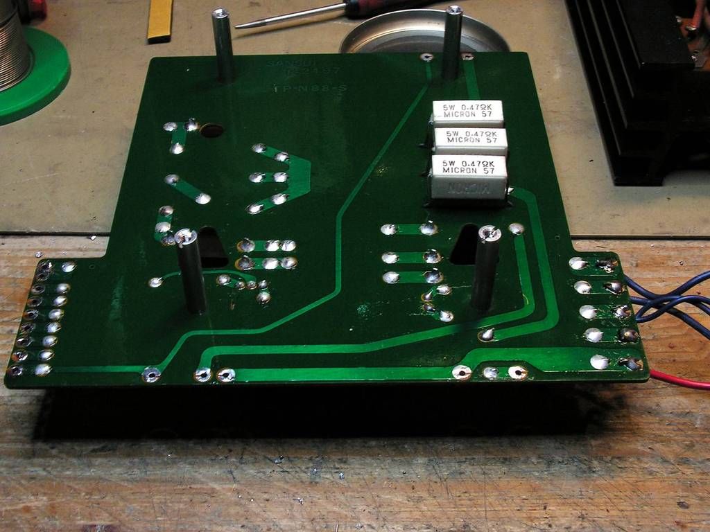
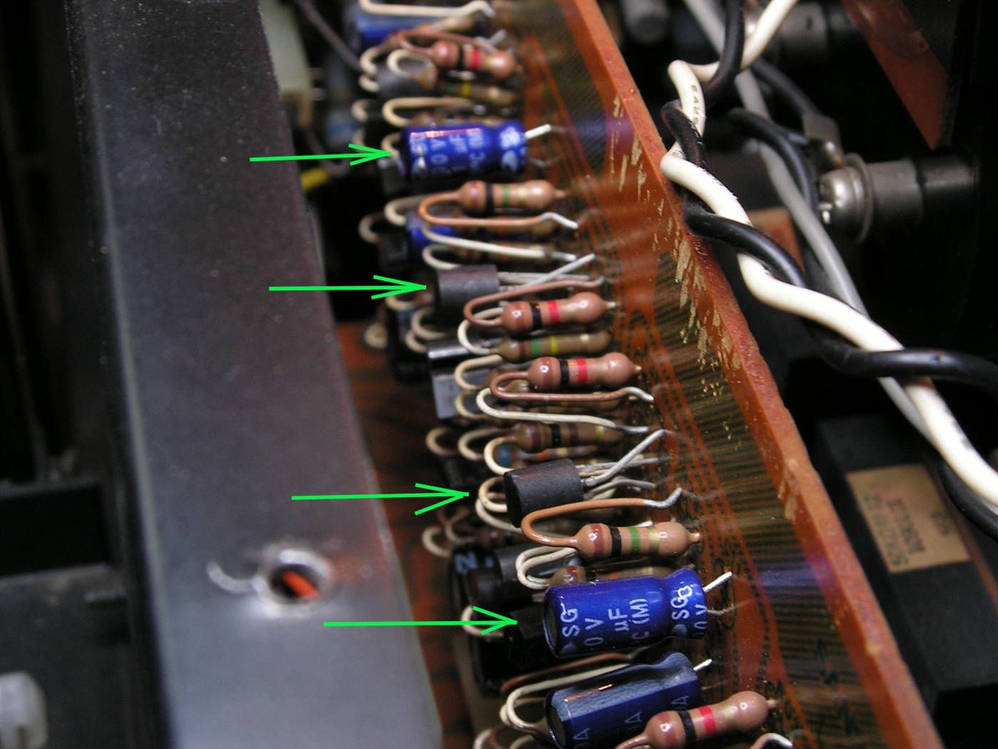
Second, that Tone amplifier board has some new electrolytic capacitors and some new small signal transistors… that will be checked later too…

PICT2706_zpsewtps8ou.jpg


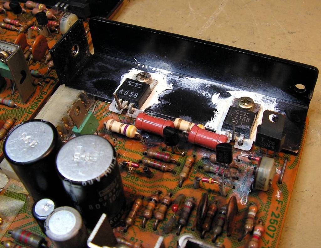
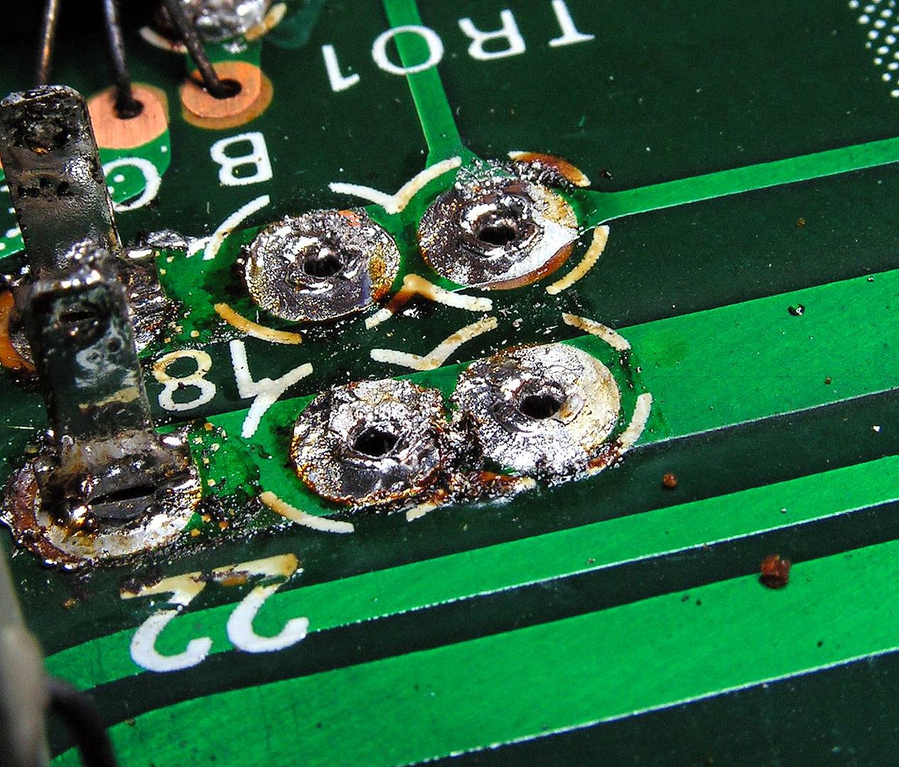
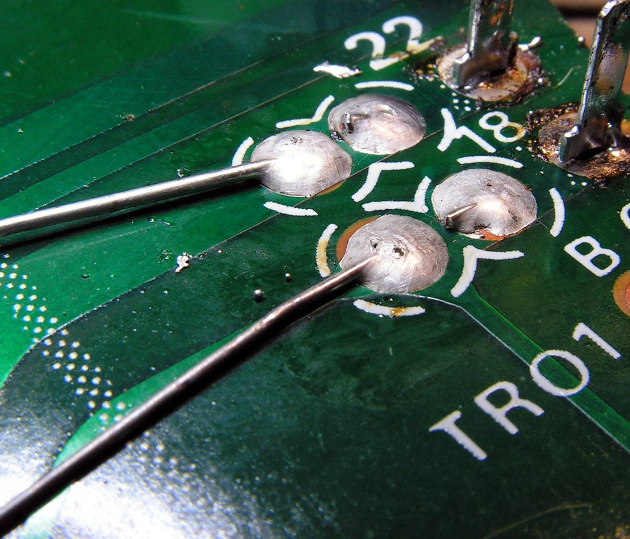
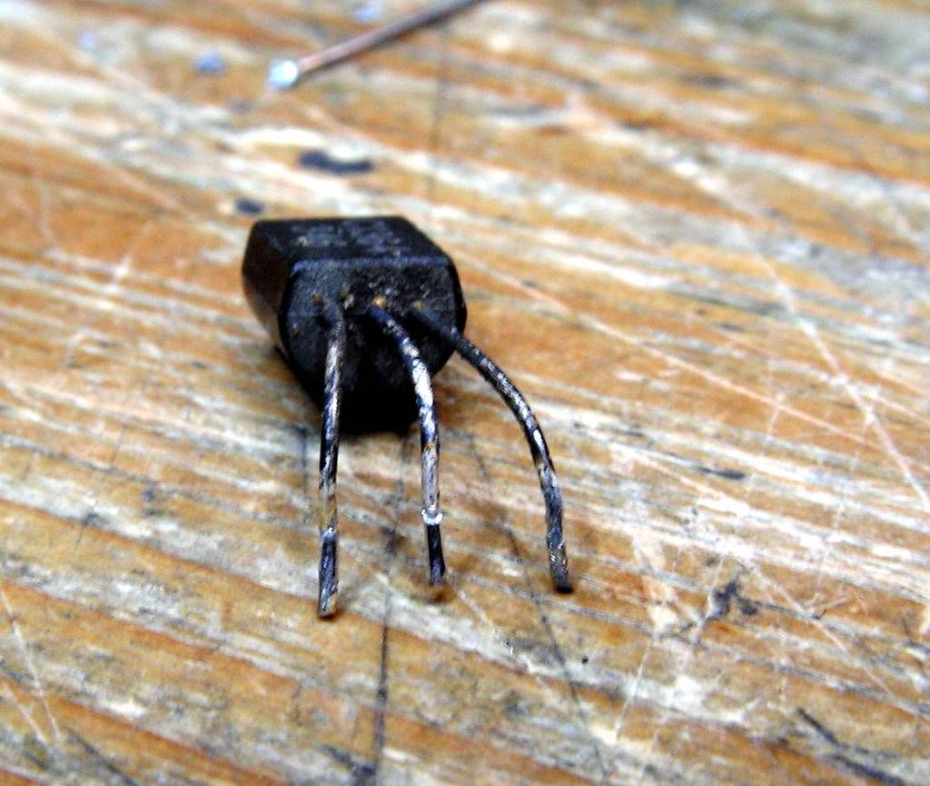
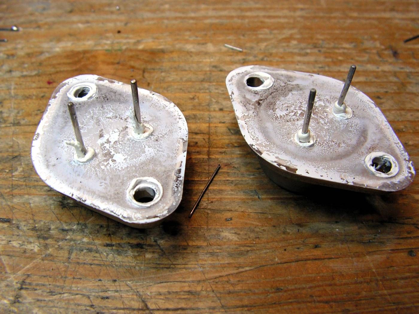
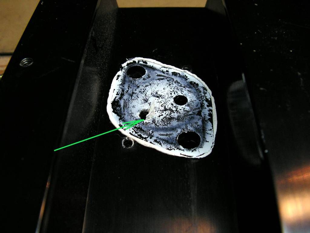
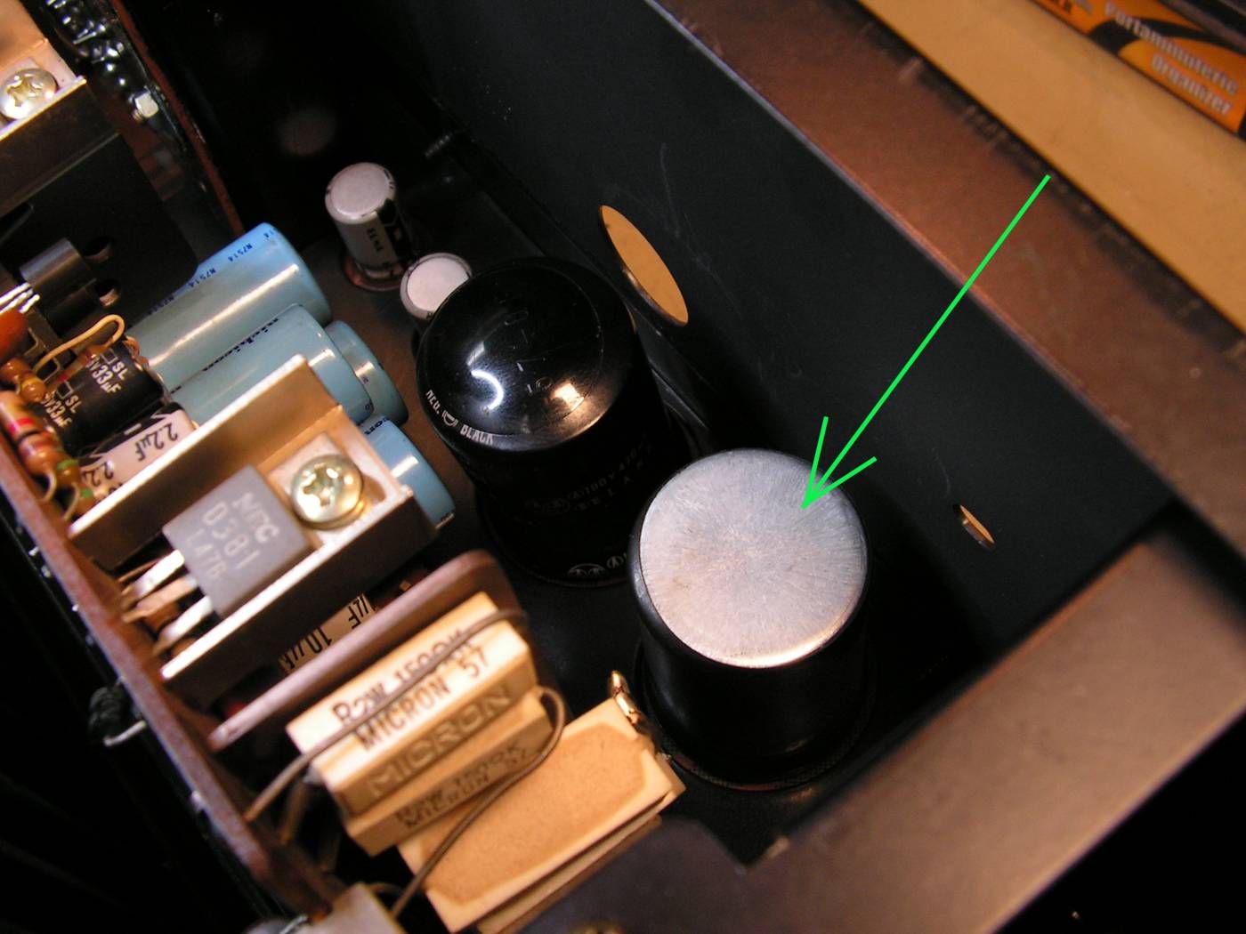
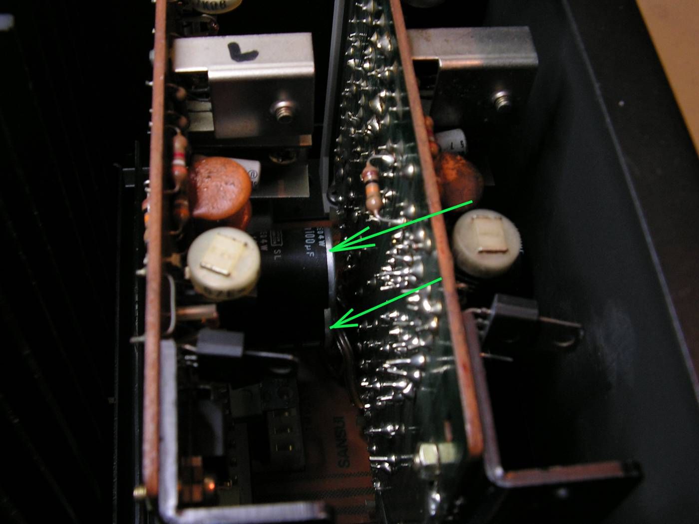
Amplifier has some overheating problems, look how looks like some electrolytic capacitors ….

PICT2707_zpstctkxztc.jpg


PICT2708_zpsmoppdcnj.jpg


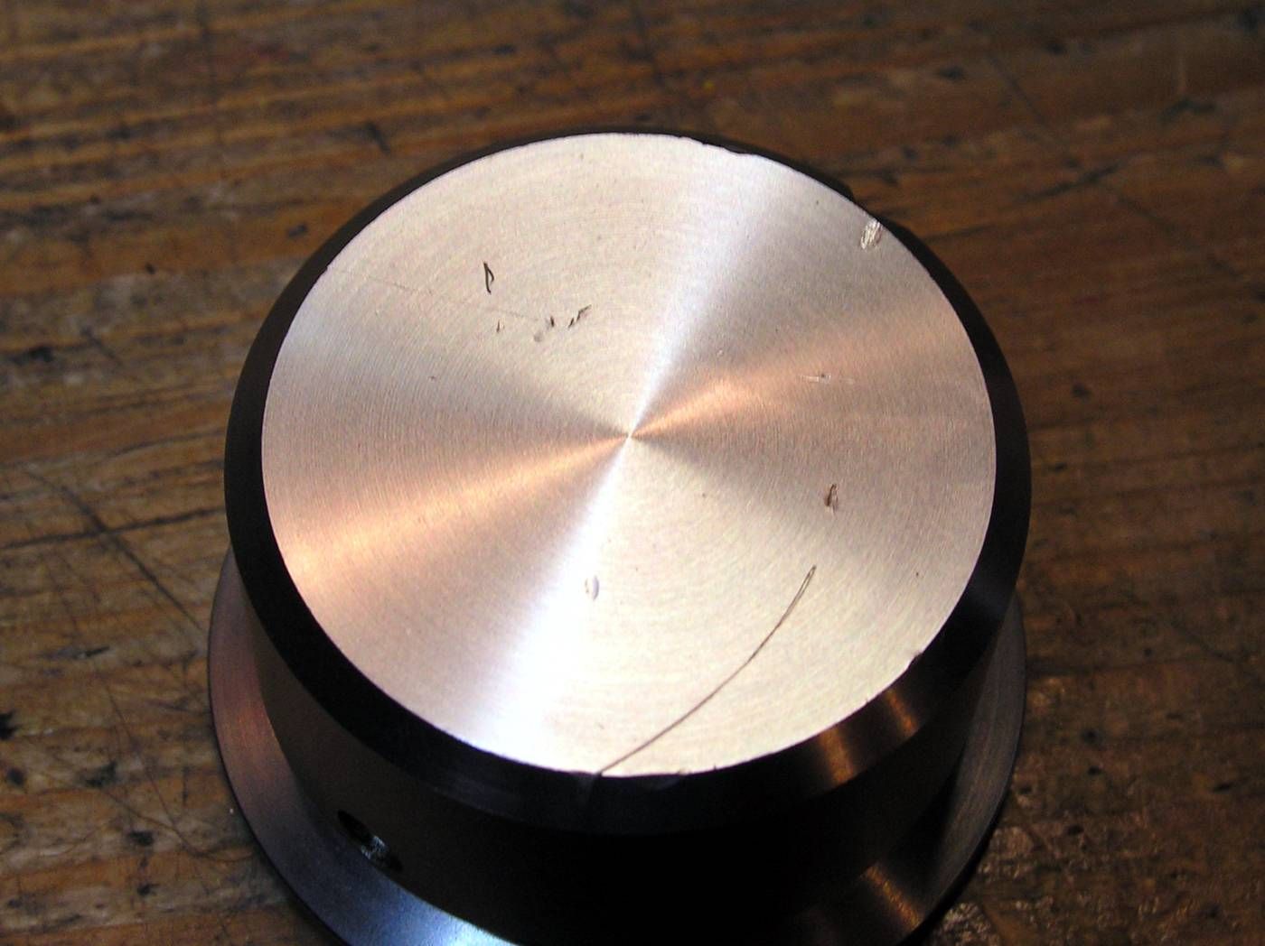
Volume knob has some scratches…

PICT2709_zpswjfatsg4.jpg


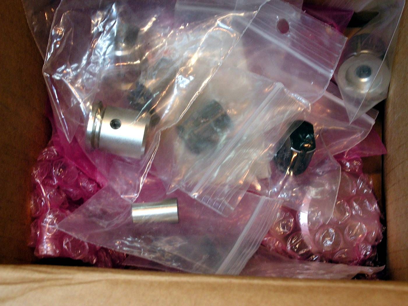
So, to prevent more damages on aluminum knobs of amplifier, I am always keeping them at nylon bags after I removed them from amplifier…

PICT2710_zpsjmbpasr3.jpg


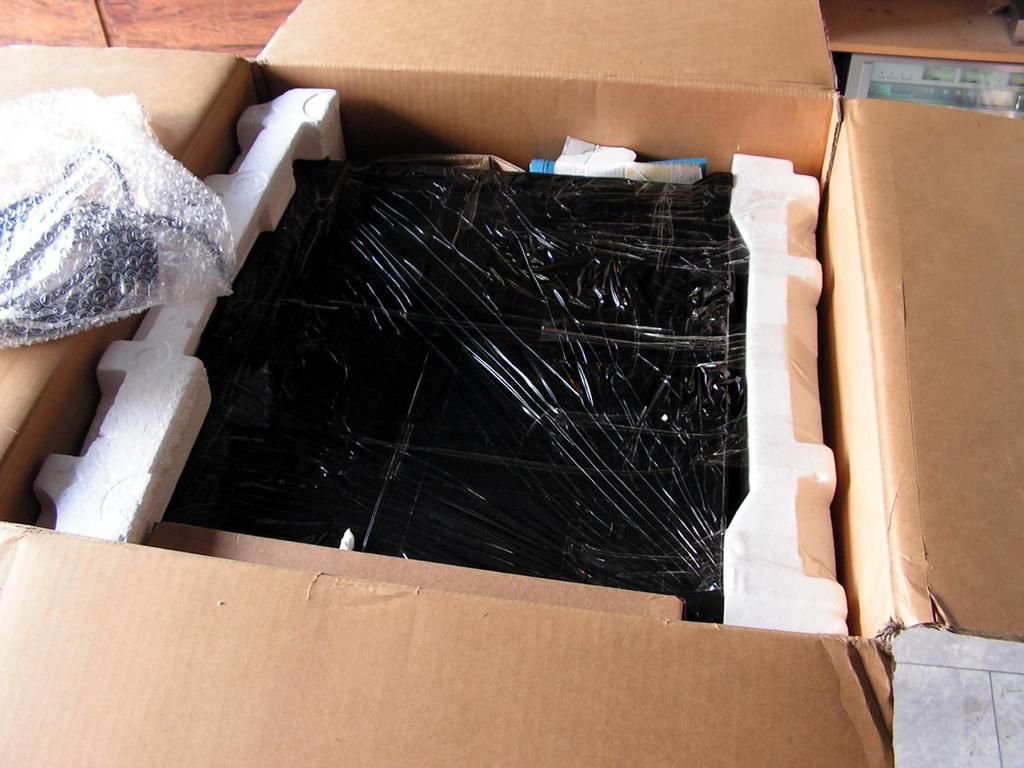
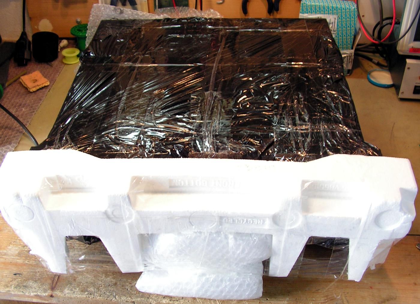
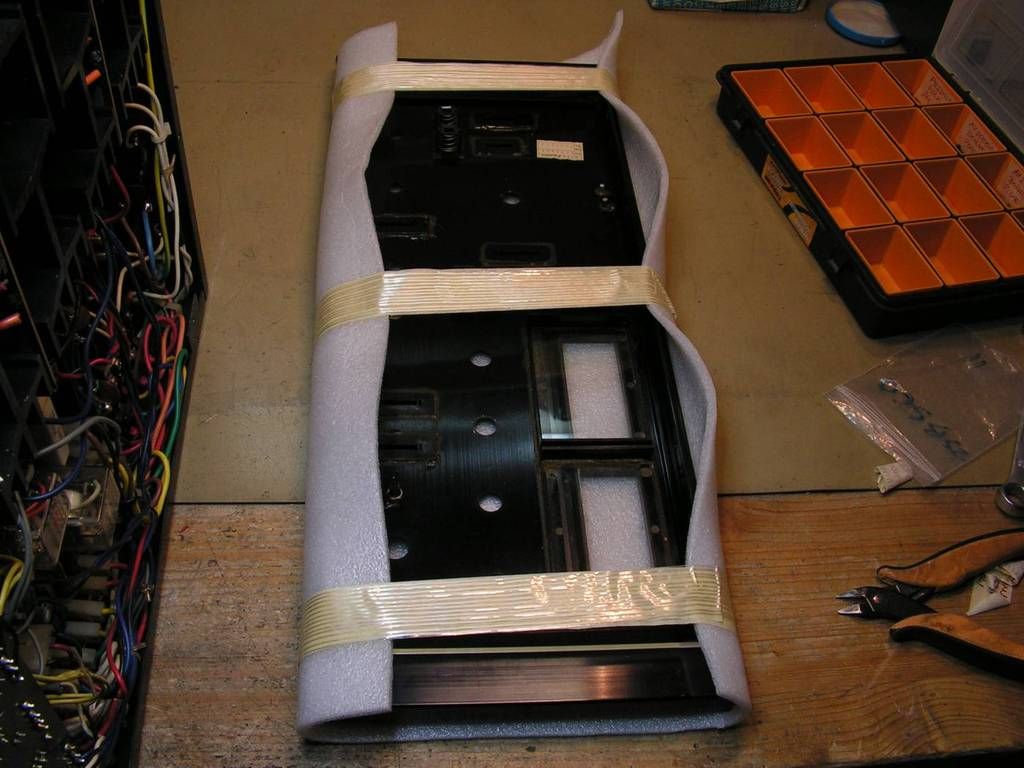
The same thing with front plate… it is protected from damage…

PICT2711_zpsdqg5jbty.jpg
 
Last edited:
Mmmm... This should be good, I can't wait to know about the power resistor on the meters. ;)
 
Driver boards… one fixed on not so nice way

PICT2741_zpswdmrzjhp.jpg


Really not so nice….

PICT2742_zpsogjanxwg.jpg


even the legs of the exchanged electronic elements are so long (technician forgot to cut them)...

PICT2743_zps8thlhgvn.jpg


The corner one of driver board…

PICT2744_zps1rwpf8fl.jpg


because the technician was not so careful

PICT2745_zpsr7c0edgv.jpg


Again overheating problem… this time on Regulated Power Supply board

PICT2746_zpsbdsunw2c.jpg


… and current state of amplifier…

PICT2740_zpsx7biac1v.jpg
 
This detail is very important at those kind of boards…

PICT2756_zpsyszmad71.jpg


That is pass through electrical connection between two side of board. As you see, that board has two side printed circuits, and electrical connection was made by that rivet. Sometime that way of connection can make connection problem, so I always remove old solder, place through hole a piece of wire, and then resolder all

PICT2757_zpsgsy2vyro.jpg
 
Another problem is this 2SC1364 BIAS transistor. Please look the next picture how it looks like:

PICT2760_zpsytayfb3v.jpg


It has a good chance to get that corrosion inside of plastic body, and them every kind of issues are possible!

So I decided to change it by Toshiba 2SC1815, but… it would be not interesting that here it is one another problem… today production of small signal transistors has plastic body smaller than that 2SC136, and that is very important, because BIAS transistor should have a good mechanical contact to that metal piece to get heat transfer from heat sink of power transistors. I solved that problem on this way:

PICT2758_zpsyqw38edy.jpg
 
Hi Kale,

Nice job :thumbsup:

i had the same issue with the bias transsistors in the AU X1, which i replaced with a new KSC1845. Are you sure this is a good permanent solution?

Polymers/foams have a time dependent behaviour coausing relaxation/creep in the material, that could reduce the contact force of the bias resistor on the heat sink. The will become more severe at higer temperatures. I am not sure how severe this is issue will be in the end in this case, but i had my doubts. It would be better to put some more stable polymer material under it.

Now i used the same solution as you did, but i am still looking for something better. I ordered some phenolic sheets of 2mm for making an adapter plate for new speaker binding posts. The plate will be mounted to the inside of the amp. The X1 has rectangular holes, but it will be CNC machined to fit to the housing and fill the rectangular holes. Maybe i will also machine some thin spacers for the bias resistors.
 
This is not a foam, this is some synthetic self-adhesive material what you can buy for putting to end of the legs for chair or table or some heavy devices. I have that material at legs of my G22000 to prevent damage of my furniture. It is very stable for pressure.

PICT2769_zpsiamaf60b.jpg
 
And how it's going to transfer the heat from the heatsink to the transistor Kale? I mean if it's synthetic (I know the kind) it's not a very good thermal conduct ant .So how the heat is going to reach the transistor , so it can vary the bias?
 
The heat sink is touching the other side (flat side) of the transistor, no issues there. The synthetic material is placed between the PCB and the curved side of the transistor (see his picture)
 
PICT2759_zpsqoaboowl.jpg


upper side of that metal piece has contact to other part of heat sink. I will show you when I would put together all parts. That grey compound is thermal silver compounds like compounds for computer processors.
 
Is there a source for the plastic connectors, male and female for these units? Mine is working however I know they are intermittent and I would love to be able to replace them.
 
Is there a source for the plastic connectors, male and female for these units? Mine is working however I know they are intermittent and I would love to be able to replace them.
The picture of that connectors would be nice....
 
I really cant understand why some technician putting so much that thermal grease, maybe he thinks that it would be better heat transfer, but not! That is worse, and in other hand, so much thermal grease could make an electrical contact problems between transistor and socket.

PICT2764_zpsejgukwke.jpg


PICT2765_zpsu7frm1hf.jpg
 
Back
Top Bottom