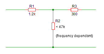
Reading back through this thread, the stated purpose the 2k2 or 300 ohm input resistor is to limit the current that some opamps drive back through the input load. Whether or not that is necessary with a typical MM cartridge I don't know.
That said, considering that at high frequency the cartridge impedance skyrockets to something near the level of the 47k load resistor and that at that point both the johnson noise and the current noise of the cart + 47k load resistor are significant contributors, the noise from the current limiting resistor is likely not worth discussing. And that's disregarding the fact that
many well respected phono stages have similar input stages.
Just to humor the question, I've done the math for the contribution of the johnson noise for the 2k2 variant.
R_1 = 2k2 Ohms (Current limiting resistor value)
T=100F = 310 Kelvin (Resistor temp estimate for room temp + case heating)
delF = 20 Khz (Frequency range of interest)
From here:
https://en.wikipedia.org/wiki/Johnson–Nyquist_noise
Using this equation but subbing in our 2k2 resistor:
1. sqrt(v_n^2) = sqrt (4*1.38e-23*310K * 2200) =
6.136 nV/sqrt(Hz) or 0.000000006136 V/sqrt(Hz)
And using our bandwidth of 20khz:
2. v_n = 6.136nV * sqrt(20khz) =
867 nV or 8.67e-7V
Assuming we've set the stage to 40dB of gain, we can expect that to be 100x higher at the output, or
3. 100*8.67e-7 =
8.67e-5V or 0.08mV.
And using the calculator here:
http://www.sengpielaudio.com/calculator-gainloss.htm because I'm tired of running numbers, and assuming a 1V reference Vout from the stage, the noise from the resistor, even after amplification by both opamp stages, is at
-81.93dB. Considering the absolute *best* you can hope for from the vinyl itself is something like 60dB signal to noise and the best turntables ever made have 80dB or so signal to noise ratios under laboratory conditions, this additional noise is a complete non-issue, even when looked at in isolation. Add in the electrical noise from the load resistor and cartridge and it becomes even more so.

")


