Any hope for this Altec 1608A?

miscrms00

Active Member
So, getting to the next step in my quest to build my budget monstrosity:
http://www.audiokarma.org/forums/in...nster-system-on-a-budget.677257/#post-9101443

Another part of my vintage theater haul:
http://www.audiokarma.org/forums/index.php?threads/intro-jbl-altec-what-have-i-done.669369/

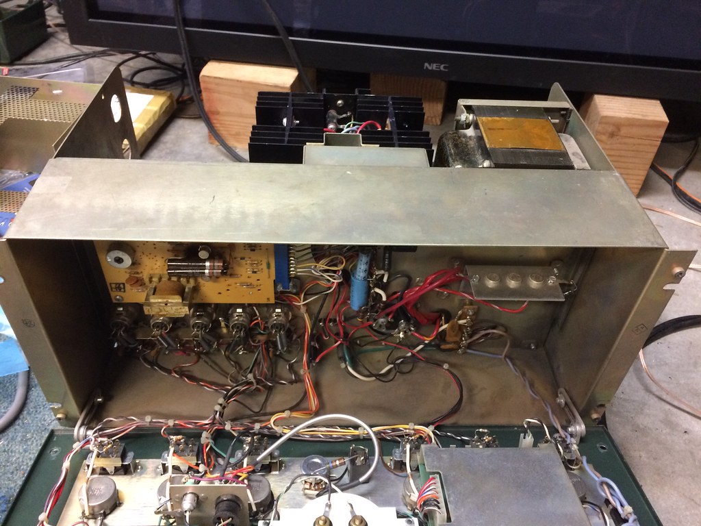
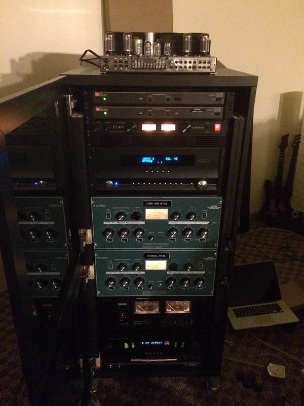
was this set of green front Altec mixers:
21458885583_2b71b25e0d_b.jpg


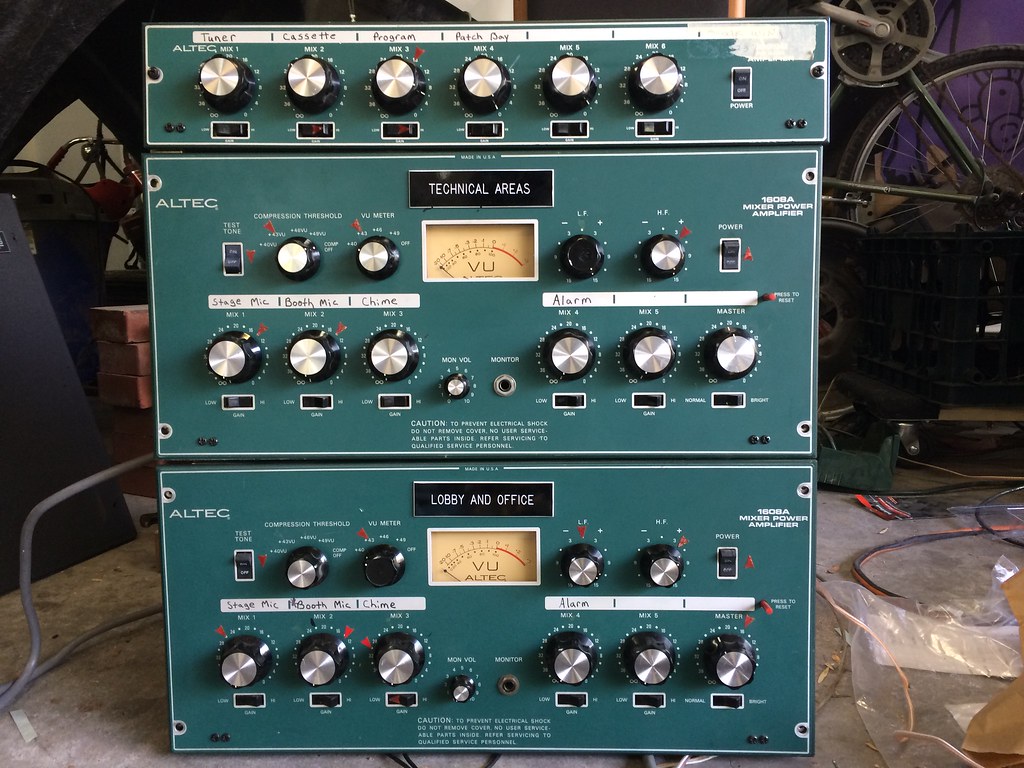
I honestly hadn't even really looked at them until I went to test them today to post on CL. Although they looked cool, I really didn't figure they would be of much use. Then I realized that they each have a 150W SS amp built in, and the one that's working sounded surprisingly good! I'm starting to wonder if I should try to save them and use them to drive my surrounds. I've still listed them on CL, if I can get enough for them from someone who wants the pre's and compressors for recording, or for a guitar amp or something I'll probably just use the proceeds to buy another vintage amp for the rears and center (was originally thinking about the JBL 6200 series, now starting to wonder about Altec 1594B or similar).

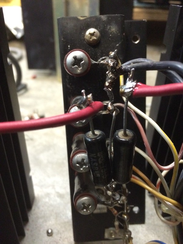
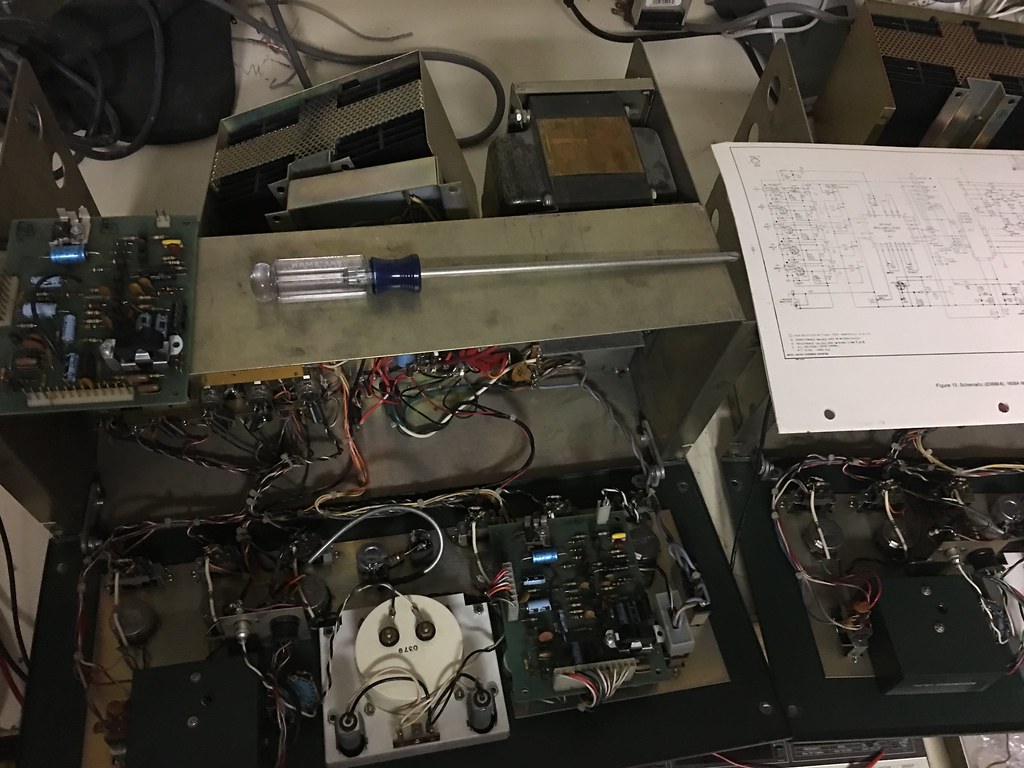
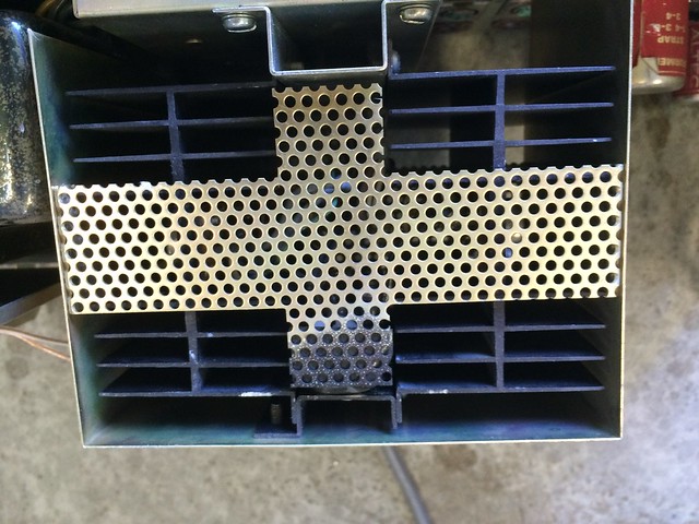
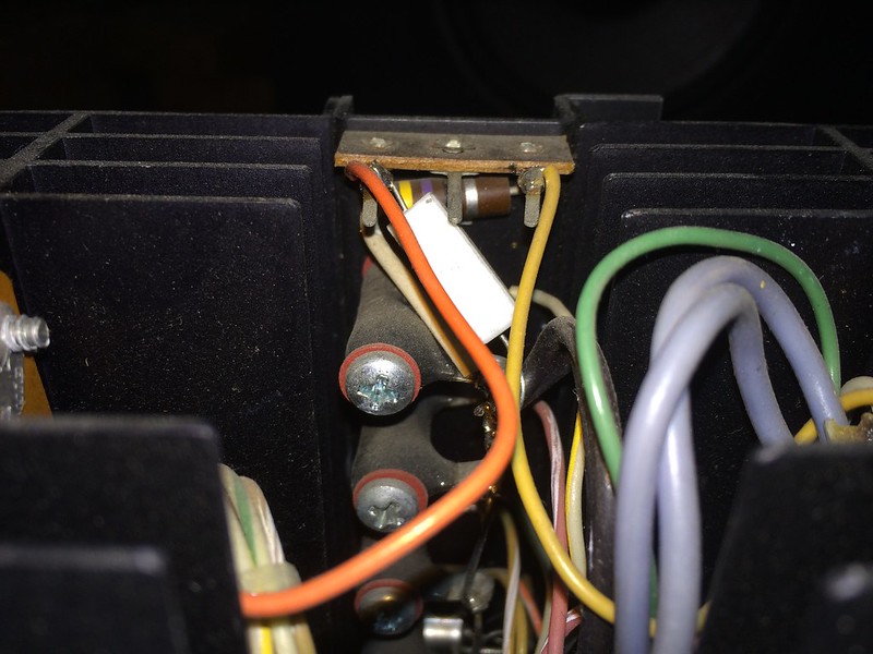
Anyway, one seems to be in good working order, the other seems to have some issues. It will pass quiet, distorted audio when powered up, but there are definite signs of trouble. First I noticed this burn mark on the back near the heatsink, and figured there might be a blown output transitor:
22053199096_a911a25784_z.jpg


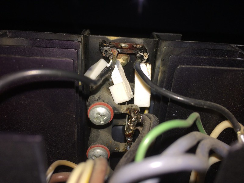
Then I removed the cover and found the transistors all look clean, its perhaps a bad connector or resistor?
21897699220_937d532b00_b.jpg


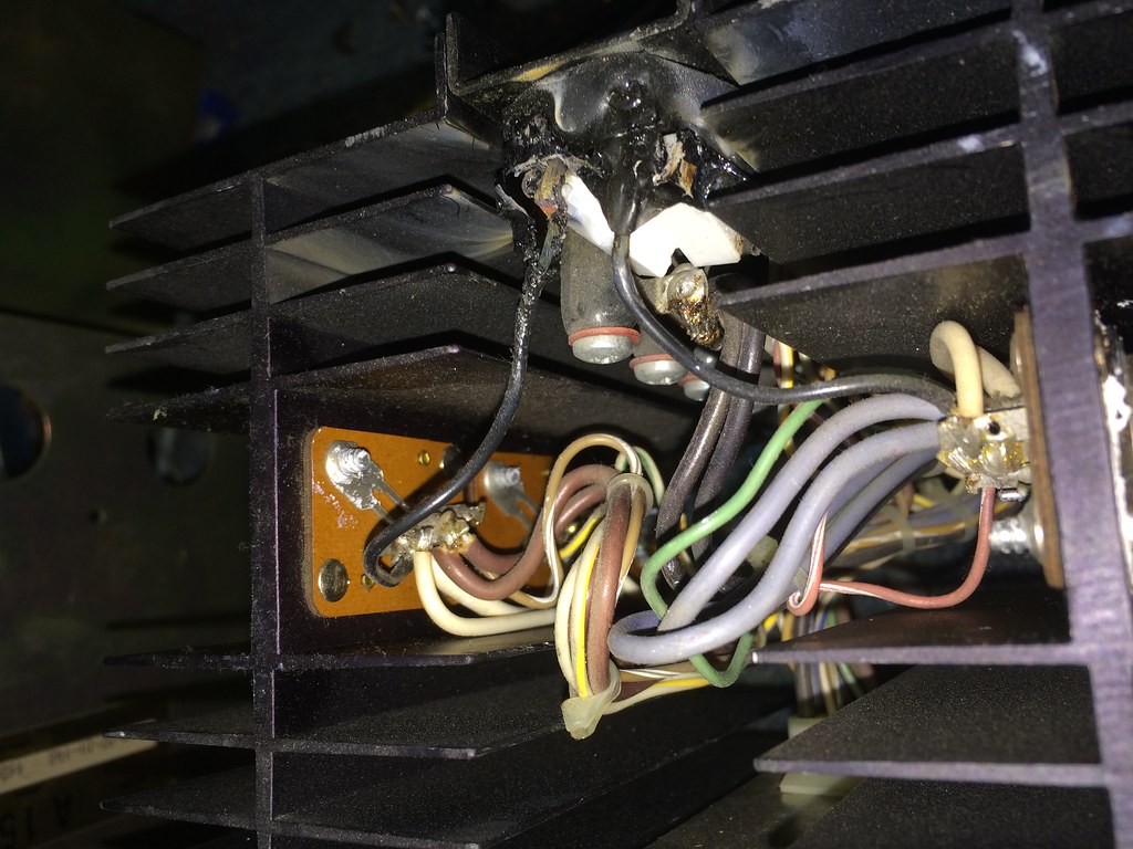
It almost looks like it had been shorting to the cage, and someone had covered it in electrical tape as a temp fix that eventually failed?

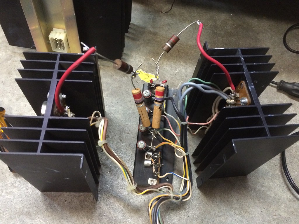
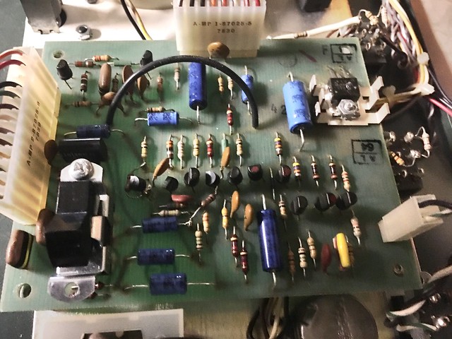
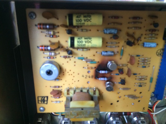
Next I found that the output devices (or at least their resistors?) on the driver card looked pretty toasty:
22095902571_387a3d8ce3_z.jpg


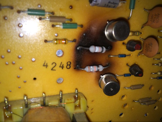
The resistors and transistors themselves actually look clean, its only the board that's blackened which I assume indicates way too much current was passed through those traces at one point. One of the resistor leads is broken though where it goes into the board. I'm guessing at some point there was a problem with the wiring out at the power device end resulting in a short that seriously stressed the driver output stage.

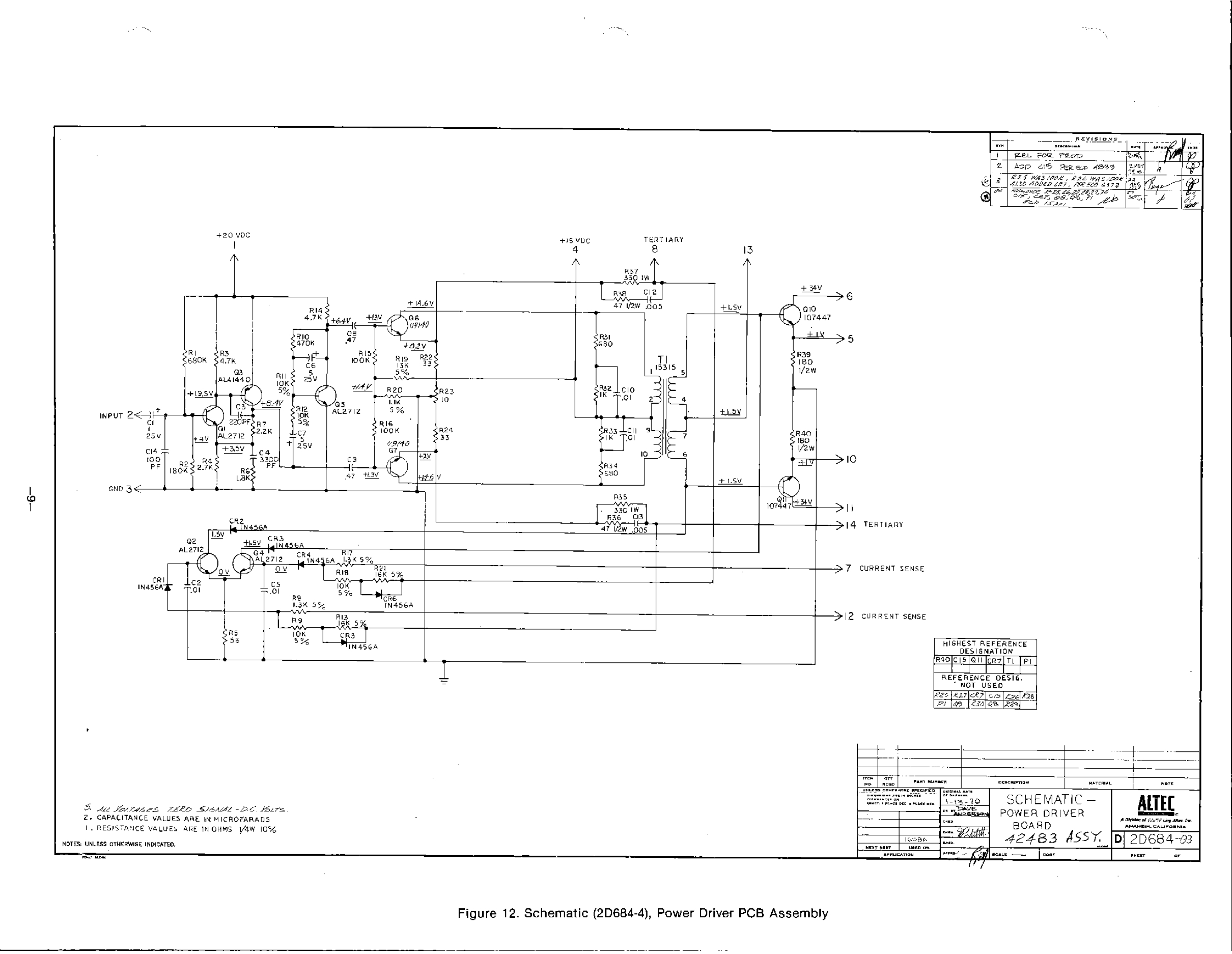
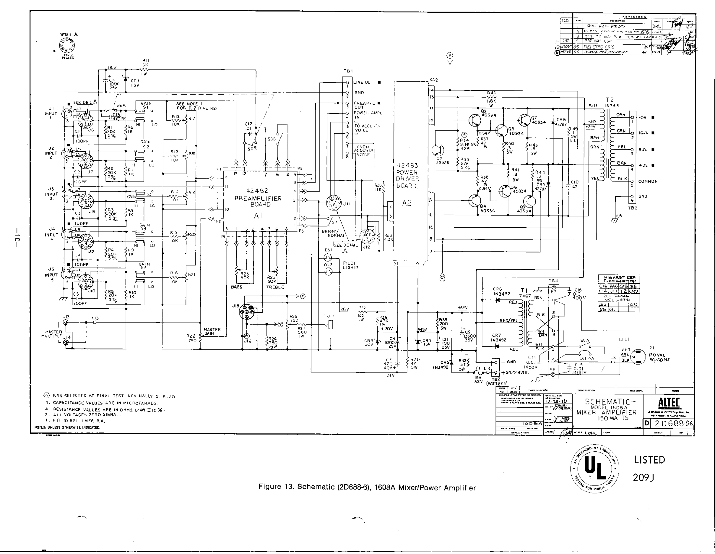
Unfortunately there don't seem to be any schematics out there that I can find. Of course I do at least have a good 1608A to compare it too. I did notice that the 1594B seems to use the same driver card, but clearly with some differences in population / wiring. This version is missing the extra pots for the "Q balance" for example (though you can see the mounting locations for them), so I assume the bias is simpler on the 1608A if nothing else?

Here's the 1608A driver card (marked 41830-14 on back):
21892491209_2d9eb298d0_z.jpg


And here's an internet image that includes the 1594B driver card:
DSC_7494_1388994448.JPG


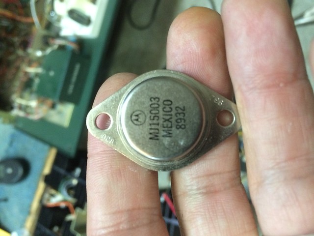
The transitors also seem to be different (which may be due to 150W vs. 100W on the 1594B?), with the driver output devices on the 1594B being listed as 2N5320, while the 1608A are 2N3440, and the output devices on the 1594B are listed as 2N6254 vs. 2N3055.

Power supply reads 34.6V, seems clean. 1594B and 1590B both show 31V supplies.

So what do you think? Can she be saved?

Rob
 
Last edited:
A few more notes. I pulled the driver card, and its pretty clear this was a previous repair. The traces underneath were damaged, and the tech had used the replacement resistor leads to reform them. In the 1594B schematic (http://brianroth.com/library/altec/altec_1594B_amplifier.pdf) these would be R126 and R127, the emitter resistors for the output drivers. I also noted one of the resistors (the one with the broken lead) was only reading 90 Ohms, when they seem to be normally 180 (same as 1594B). I pulled both and replaced with some 2W 180 Ohm I had lying around to see if that helped. Everything ohms out ok now to the pins of other devices, so even with the damaged traces there seems to be connectivity.

On power up I noted that there is ~20V dropping across these resistors and they are heating up fast. On the 1594B this node is labeled as 1V. So something is definitely still out of whack there.

As luck would have it there happened to be a NOS driver card on ebay for a reasonable amount of money, so I pulled the trigger on that. This one is pretty damaged, even if it turns out to be ok so I figured I might as well grab it. Can't imagine those come along very often!

Also looking at a preview of a copy of the manual on ebay it looks like the 1608A originally had 2N6254 out transistors, same as the 1594B. So some of the transistors may have been changed on this one. It also looks like it has a newer power supply filter cap.

I may have to bite the bullet and just buy a copy of the schematic to see just how similar to the 1594B it is. Maybe the difference in power output is just because the 1594B has a THD spec? It also looks like the transformers are different. 1594B looks to use peerless, don't think these ones are.
 
I did find out that the output transformer is a Peerless 16745.

I did also find the specs, 150W at 1% THD from 45Hz to 12kHz, +/- 1dB from 20Hz-20kHz. The 1594B is spec'd 100W at 1% THD 35Hz to 20kHz, 100W at 0.5% THD 50Hz to 15kHz, +/- 1dB from 20Hz-20kHz.
 
Last edited:
So, I decided to go ahead and do some board swapping and see what I could find out. The bad unit works fine with the Driver board and output block from the good unit. It also still works fine with the damaged / repaired driver card reinstalled. So that pretty much narrows it down to the output block on the bad unit. From the pics below it looks like the replacement resistors for what would be R2 and R3 on the 1594B schematic (1608A looks to be 47 Ohm instead of 22 Ohm) have been stressed. Have to start taking things apart and seeing whats what.

Good unit:
22108592451_aa11c35105_c.jpg


Bad Unit:
22108592431_1c3f3dc390_c.jpg
 
Latest theory. Using 1594B part numbers, failed output device(s) caused R2/3 to overheat and fail open. This caused R126/127 on the driver card to overheat.

I replaced R2/3 with 2W 27 Ohm (closest I had, between the 1594B 22 Ohms and the 47 Ohm there previously). R126/127 no longer overheat, but R2/3 now get very hot, noise on output. Replaced Q5/6 with RadioShack 2N3055, same behavior. Replaced remaining 4 2N3055. Same. Added 15 Ohm 2W resistor to get to ~50 Ohms on R2/3. Now only left side R gets hot. Pulled output transistors on that side, 2 shorted. Checked old output devices, 2/6 shorted. Put 4 "good" old devices back into Q1,2,3,4. Noise on output gone, all Rs now cool. Voltage drop on R2/3 now ~0.5V, similar to good output block. Audio plays at decent volume, but pretty distorted. Getting closer ;)
21496695594_f2908f56ac_b.jpg


Found a bunch of NOS Motorola MJ15003 all with same date code at my favorite local reclamation shop. Going to at least check Hfe and Vbe with my DVM to pick the closest 6/18 and give them a try. Can take in to work and do a more detailed matching if still seems necessary....
21496695614_660e507516_z.jpg


Also found some NOS IRC 5W 1% 47.5 Ohm resistors that should do nicely. All 47.8 Ohm by my cheap DVM.
21931646898_5105ef2205_z.jpg


Rob
 
The equivalent of 1594B R2/3 look to be 1W 47 Ohm, rather than 1W 22 Ohm. That's what they are on the good unit at least, although only one looks potentially original as pictured above.

These are the emitter resistors on the input pair of the output block. Not sure what you'd call them, they almost look like followers to provide the base current required by the output devices, but the fact that they share the inductive transformer load confuses me a bit.

The emitter resistors for the output devices (equivalent to R4/5/7/8 0.5 Ohm 5W on the 1594B) are 0.3 Ohm 5W.
 
Making progress!! Installed the new R2/3 resistors, and selected MJ15003s for the output block. Distortion is gone, sounding pretty clean now! Still a bit noisy, and this one seems to have some issues in the tone control section but all in all a big step forward :) It will be interesting to see if its any quieter when the NOS driver board arrives. I have also had a few what I assume are "stability events", so may some work to do there. The MJ15003s may be a bit faster / higher gain than the original 2N6254s. Its only happened when I've been poking around inside the front panel, so maybe its something else all together. Its a little suspicious that this unit has a big red "reset" button on the front panel. I wonder if stability was always a little marginal on these?

Here is the distribution of the Hfe and Vbe on the 18 MJ15003s I picked up, and the devices selected. I realize this is not real accurate since I'm just using a low current DVM measurement, but hopefully its better than nothing ;)

21939976200_5a5f7b18fa_z.jpg


The insulator block was pretty toasted, so had to bypass for now.
21518955833_73354b22b6_c.jpg


All back together:
22140063365_6a156c8f6f_b.jpg
 
I'm officially doing a happy dance :) Crappy iphone mic doesn't do any justice to the sound, but here's some dancing needle goodness! Went back to the recycler today and found a perfect match for the missing fuse holder cap, and a NOS box of panel lamps. First time I've been able to hear both amps together. Might have to test my supply caps, not sure the meter lamps should be dimming quite that much ;) Meters are on the lowest setting (+40dB). Audio tools says they are pushing about 100dB out of the JBL S38s in the "shop" right now.


I think I can take this one off the endangered species list :)

Rob
 
Well, now that I'm putting it into the rack I've picked a pretty good transformer buzz. First time it went in seemed fine, then I re-ordered the amps to try and improve air flow and now its buzzing. I'm hoping its just the location, and its buzzing against the metal case of the component below. Going to pull it out again and see what's what.

21687264844_8143ca1b48_c.jpg

22284339136_dc183dca80_c.jpg


Was fine when they were under the pre/pro, there's a pretty good gap to the amp below. But now the pre/pro is just under, and its sitting flush against the case. Hopefully that's all its is...
Rob
 
Man, that is elegant! Great job on documenting what you were having to deal with. Frankly, I'm getting lazy in my old age and would have found a more willing person like yourself to deal with it.

I never realized how nice the Altec green mixes with other gear. The VU meters help the contrast, too.

Great job, Miscrms00.

Cheers,

David
 
Well, now I've done it. This is a real puzzler. I pulled the amp back out of the rack last night and the transformer buzz was better out of the rack, but still definitely there. So I gave the transformer cover bolts a bit of a tightening (while powered on so I could hear any change) and the amp goes unstable! Now it doesn't seem to matter what I do tighten, loosen, amp is unstable every time I turn it on!

I'm at a bit of a loss for what changed. Measured all the DC supply voltages, still look good. I did notice that turning the compressor on changes the nature of the instability from constant high frequency (mostly inaudible) to more periodic pops. Also the tone controls influence the strength and nature of the instability. That struck me as interesting as the compressor / tone controls are in the pre-amp, before the driver / output stages and their associated feedback.

I think I'm going to start a new thread on this one to seek out more general input...

Ah the joys of vintage gear ;)

Rob
 
Also, since I couldn't find schematics anywhere online I broke down and bought an original operating manual on ebay. I can't seem to get the full PDF I scanned to upload, but here are scans of the schematics.
21793866443_536b3eb8f9_o.jpg

21792233184_d63a00543b_o.jpg

22401780802_800f7a2af8_o.jpg
 
What a cliff hanger!! It'll be as close as I'll ever get to hearing one of these. Hope you get it running to your satisfaction.
 
I can't believe its been more than a year!?!

Well, I finally got some time to get both Altecs on the bench and do a side by side with the good one and the bad one. Then started swapping parts from the good one into the bad one to try and figure out what the heck is going on.

First noticed the power supply voltage is a bit low on the bad one, 31V vs. 34V. PS cap on the bad one measures worse than the good one, even though it looks newer. Swapped the caps, no changes.

Swapped the Power Driver boards, no change.

Swapped the output device blocks, no change.

Starting to fear the transformer may be damaged, measured with Ohm meter and Impedance Analyzer, seems the same as the good one. Can also hear the tones from the impedance analyzer on the speakers, seems same on both.

Disconnected the pre-amp board. Power Supply up to 34.9V. Hmmm. Swapped in the good amps pre-amp board. Still 34.9V, and no oscillation. Hooked up music. Sounds fine.

So it seems like I've at least narrowed it down to the pre-amp! Apparently just co-incidence with tightening the transformer bolts? Anyway, will have to start trying to hunt for what's gone wrong.

31475904704_334eda1536_b.jpg
 
So, interesting discovery today.

I had traced out both the good and "bad" pre-amp boards comparing resistors, diode junctions, caps on the impedance analyzer, and finally voltages to each other and to the schematics. There are a few differences to the schematics, but they are pretty much the same on both boards. In general everything looked pretty similar. But with the good board in, I get music. With the bad board no music even when its sometimes not noisy, and lots of clicks and pops or motorboating when it is. Was getting pretty closed to stumped.

This morning I tried just touching a wire from various ground points on the pre-amp board to the chassis. One pop, then quiet then music, pretty much wherever I touched it. Nothing but noise as soon as I released. So I checked the DC voltage between the pre-amp ground and its ~3.5V. With the "good" board back in 0V. So I'm guessing something like a PS cap is leaking causing the ground voltage to rise relative to the chassis? Not entirely sure why this would cause my problem, maybe an offset somewhere or noise coupling through ground? But I'll take it :) Will probably go through and replace all the supply caps on the pre-amp board and see what happens from there....
 
Motor boating would have me looking for a bad electrolytic cap. That setup looks so cool! I hope you get it up and running.
 
So, I ordered a full set of electrolytic caps from digikey, should be here Friday. Hopefully will get them installed this weekend.

In the mean time, I think I found the culprit. I was thinking more about how I could be developing voltage between the amp ground and chassis ground. That didn't seem to make any sense. From what I can see in the schematics the amp ground and chassis ground should be isolated. There would have to be a leakage path and current flow between the two grounds in order to get a voltage across them. One of those ohms laws kind of things ;) Leakage through a bypass or coupling cap shouldn't be able to do that. Of course immediately I start worrying about the transformer again...

So I measured the resistance between the DC ground side of the main PS cap and the chassis and its off scale >20M Ohms. Not a proper leakage test perhaps, but encouraging. Plug in the "bad" pre-amp board, and its -4M Ohm. Hmm. Swap in the good pre-amp board and its back to off scale >20M Ohm. Now I'm really confused, as I can't see any connection between the pre-amp board and chassis ground. Its not even screwed down and its 100% repeatable between the good and bad boards, so I'm pretty sure its not just shorting to the chassis somewhere. Plus, the "-4M Ohm" reading doesn't sounds like a short, more like a bad cap...

So I start ohming out the wires coming into the pre-amp board to the chassis, and the first one I check P2-1 is 0M Ohm! It turns out the "Master Gain" pot is not isolated from the chassis. Not sure if its supposed to be, but its not. Normally this is not an issue I guess, as its connection to the input gain stage is AC coupled through C14. So I ohm out C14. Sure enough, -4M Ohm on the bad board, >20M Ohm on the good board! I can't check it right now on the impedance analyzer, as I accidentally blew the input fuse by powering up the amp while it was still connected (replacement fuse is also on the way from digikey), but its pretty likely this cap is leaking on the bad board allowing DC current to flow from the input stage to chassis ground through the master gain pot.

Seems like this could probably provides a direct path for noise to couple right into the input stage giving a nice feedback path.

I'll check back in once I swap the caps to see if that was it, but I'm optimistic :)
 
FYI here's what I ordered for caps. I went ahead and bought enough to do both chassis, both pre-amp boards, and 3 power driver boards (including the spare I picked up a while back). All told that ran about $160 with tax and 3 day shipping. I figure if everything works out ok on the bad board and it sounds good, then I might as well do both amps while they are out on the bench.

I went with the Vishay ASM 021 series for the bulk of the caps. Partly because there aren't many options for axial electrolytics on digikey, and I wanted to stick with axial, order from one place, and get them quickly. And partly because after a bit of digging I found several threads saying they are actually quite decent, being a continuation of a respected Philips line. And at least a little bit of it had to be that the old school blue metalic cans look cool :) They also spec both 100Hz ESR and 10kHz impedance and seem to do pretty well at both, in fact I found a set of test curves one guy had done showing they seemed to compare favorably to the Nichicon KZ. I ended up buying the 63V versions for most sizes as there was room and they had even better ESR/impedance ratings, while 100V were too big and/or specs were similar or worse. I've also read the Vishay AML 138 series sounds just as good, but are the longer life 105C version. I didn't go that route at this time as they were about 2x the cost, and they don't have the cool blue metallic cans ;)

On closer look, I suspect the existing output caps on the pre-amp boards are also Philips, so that's convenient :) They are blue metallic cans just marked 100uF - 40V -10/+50% 016 - Mexico J 9, but Philips did make an 016 series and the blue transparent wrapping over metallic can looks very Philips.

So here's what I ended up ordering. Note there are some differences between the BOM, schematic and what's on my boards as noted. It's possible mine had already been rebuilt once, they are both identical but they also both came out of the same concert hall. My old spare power driver board was claimed to be NOS, and has older looking plain metal cap cans on it. It does also seem to be an older revision of the board though.

Pre-Amp Board
C1,9,15,16,21: Schem: 10uF/25V, BOM: 10uF/50V, Board: Rubycon CE W 10uF/50V, Replacement Vishay ASM 021 10uF/63V
C14,18: Schem: 50uF/25V, BOM 50uF/25V, Board: C14 Rubycon CE W 47uF/25V, C18 unknown black GN 47uF/25V, Replacement Vishay ASM 021 47uF/63V
C17: Schem: 25uF/25V, BOM: 25uF/25V, Board: unknown black SL 25uF / 25V, Replacement Vishay ASM 021 33uF/63V (choices were 23uF or 33uF, going lower seemed risky with tolerance)
C22: Schem: 100uF/25V, BOM: 100uF/35V, Board: Phillips? 016 100uF 40V, Replacement Vishay ASM 021 100uF/63V

Power Driver Board:
C1: Schem/BOM: 1uF/25V, Board: Rubycon CE W 1uF/50V, Replacement: Vishay ASM 021 1uF/63V
C6,7: Schem/BOM: 5uF/25V, Board: Rubycon CE W 4.7uF/35V, Replacement: Vishay ASM 021 4.7uF/63V

Chassis:
C7 (31V supply for pre-amp): Schem/BOM: 470uF/40V, Actual: Siemens Orange 470uF/40V, Replacement: Vishay ASM 021 470uF/63V
C6,8 (15V accessories, 20V power driver): Schem/BOM: 1000uF/25V, Actual: Mallory TC 1000uF/25V, Replacement: Vishay ASM 021 1000uF/63V
C9 (main 34V rail): Schem/BOM: 13500uF/35V, Actual: Mepco/Electra 1st EF 10,000uF/100V, 2nd EE 13,500/35V, Replacement: TDK/EPCOS B41458 15,000uF/100V
C11 (15V power driver): Schem: 100uF/25V, BOM: 100uF/35V, Actual: Rubycon CE W 100uF/35V, Replacement Vishay ASM 021 100uF/63V
 
So... Apparently my theory was wrong. ;) But luckily, its working now anyway! :)

Replaced C14, no change. Replaced the output cap C22, no change. Replaced all the remaining electrolytic caps, still no change. I guess that explains why they all seemed ok on the impedance analyzer. As a last ditch effort before having to start replacing more components (that also all seemed ok, but not able to test conclusively) I reheated every connection with the iron, sucked most of the solder off and resoldered. I couldn't see any bad joints, but apparently there was at least one. I was just going to reflow each, but the old solder didn't seem to melt and reflow well. Seemed safer just to pull most of it off and redo it.

Sadly the Vishay ASM 021 caps don't still have the old school transparent blue / metalic wrapping, but I guess I'll get over it. ;) It was nice to see the Country of Origin: Austria on the packaging, which seems to confirm their Philips / BC heritage. They are also really small. Even going up to 63V most are significantly smaller than the ones they replaced. I guess that's usually not a good thing in audio caps, but we'll see....

32368384986_d76c5786f1_z.jpg


Since I have them, I'm still planning to go ahead and replace the rest of the electrolytics. I will do a bit more listening comparing the two pre-amp boards, but my initial reaction is the new caps sound fine. I don't claim to have a very picky ear though... ;) Will probably go ahead and re-cap / re-flow the other pre-amp board as well then do the power boards (only 3 caps) and the chassis power supply caps.

It would be nice to know exactly what happened, but I'm just happy to have it working again :)
 
Back
Top Bottom