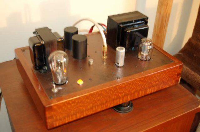
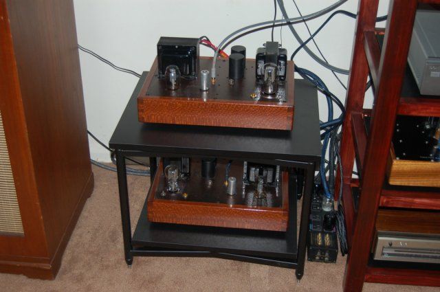
Anyone ever do a loftin-white?

maxhifi

AK Subscriber
Subscriber
Am finishing up plans to build two mono direct coupled 6SF5 - 2A3 amplifiers. Will have an LCLC power supply with a 5U4 rectifier on each monoblock, and AC on the output tube heaters.

All large capacitors to be polypropelyne film, no electrolytic capacitors.

Anyone here try a loftin white? Impresaions ? I am
Excited to give it a go. My existing amp is a 91A style with an EF37A capacitor coupled to the 2A3.
 
I haven't built one yet, but I've been looking into it. You will want to think very carefully about what happens to the output tube when the driver tube is absent or failed.
 
I had a Loftin White built by James Burgess....I loved the amp.
1930's tubes, the RL 12 T15. The driver tubes are PC86's and the rectifier in each amp is the Telefunken AZ-1.


I haven't built one yet, but I've been looking into it. You will want to think very carefully about what happens to the output tube when the driver tube is absent or failed.

The plan for that is basically just to use high quality (not Chinese) tube sockets, and make sure the driver tube is well tested. It is definitely a risk which is being taken on, but the amplifiers will only be used and serviced by me, and used under my supervision, etc.


I had a Loftin White built by James Burgess....I loved the amp.
1930's tubes, the RL 12 T15. The driver tubes are PC86's and the rectifier in each amp is the Telefunken AZ-1.


Those are very attractive looking amplifiers. Any comments on sound quality versus a more conventional design? The one thing I am slightly concerned about, is the high resistance bias resistor on the 2A3 affecting output impedance, although really the bypass cap should make that a non issue.
 
You are on the right track to really good sound!

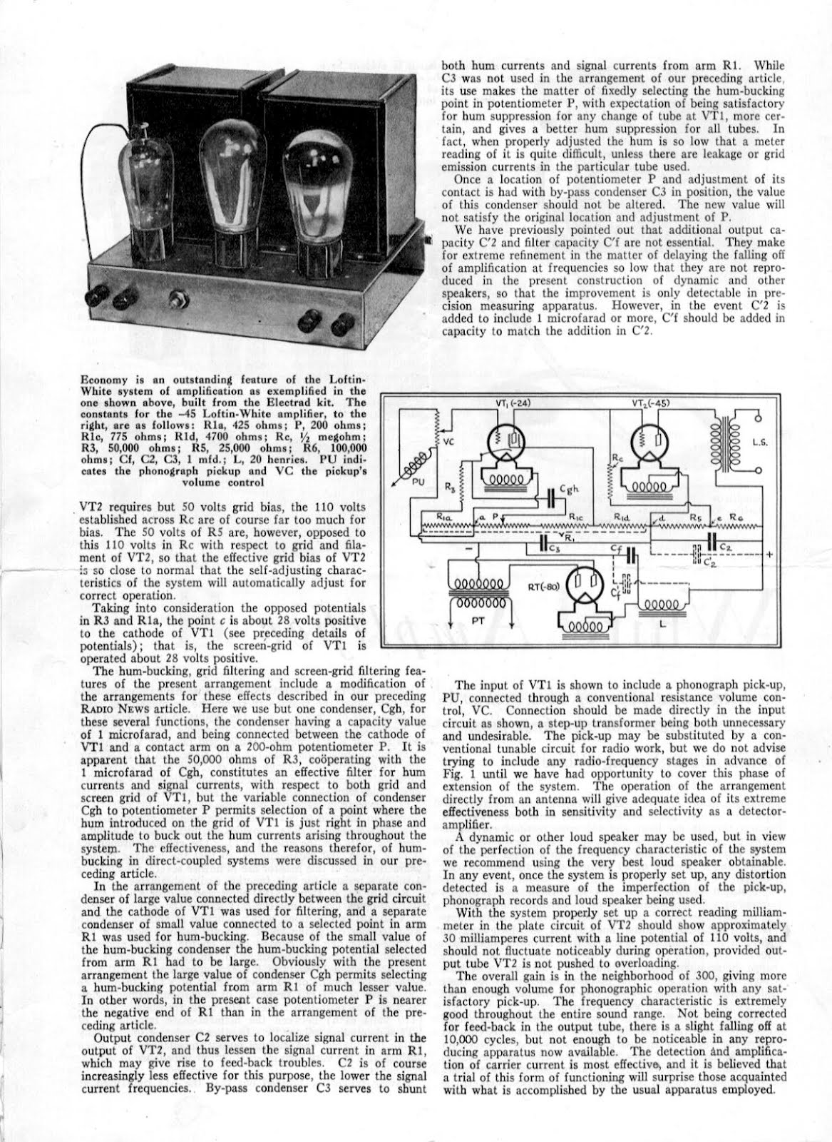
There are many variations on the Loftin/White theme; some could even be called an accurate Loftin/White circuit and some are simply "inspired" by Loftin/White. I would be curious to know which circuit you are considering. A true Loftin/White seems to me to have four key elements:

1. The driver tube is direct couple to the output tube.
2. The driver tube gets its plate supply voltage from a voltage divider in the output tube's cathode.
3. The last capacitor in the power supply is also the bypass capacitor for the output tube's cathode resistor.
4. A high mu triode is used as a driver for the 2A3.

Many of the "so called" Loftin/White schematics fail to implement #3. I would call them "inspired" by Loftin/White. I would also call the "Monkey" and the "DRD" amps "inspired" by L/W since they omit #4, replacing the high mu triode with a high transconductance triode.

My own experience is primarily building the monkey/DRD amps, although last year I built an amp that employed elements #1, #3, and #4; that's to say I didn't derive the driver tube's plate supply from the output tube's cathode resistor. So as you can see there are many variations on the L/W theme; that's why I was curious which schematic you were considering. Each of the above topologies has some elements that make for good sound, but the critical element is direct coupling. Eliminating the coupling cap is a KEY component in the great sound. Loftin/White eliminated the coupling cap for practical reasons: good caps in the 1930s were expensive and unreliable, so they found a way to eliminate it. In the 21c. we have very high quality capacitors available to us, but the best are still expensive. In the end, the real reason to eliminate the coupling cap is because the very best capacitor is NO capacitor. So, whichever topology you choose be prepared for some juggling of resistance values in the cathode of the 2A3 to get both the driver tube and the output tube to operate in their most linear regions. This is not really an amp for a first time builder as it requires some "fine tuning." The builder should be comfortable with Ohm's and Kirchhoff's laws and have some test equipment.

Here's an amp I built last year that is "inspired" by L/W. Notice it used the 6K5 instead of the 6F5 and the difference is that between the 6SL7 and the 12AX7 (mu and transconductance). Notice also that I eliminate #2 above. This is simple to build and you can substitute a 100Kohm resistor for the CCS but you will have to compute the 2A3 cathode resistor based upon your power transformer's voltage and driver stage plate voltage. Also note that because of the low transconductance driver, the driver can't push the 2A3 to full output because the grid current starts about -60V and disrupts the 6K5 linearity; it would be the same with the 6F5. This is a very good sounding amp: very clear and dynamic.

2A3 amp 6K5 driver stereo.jpg

Here's an example of the monkey/DRD amp. Note that this employs a high transconductance driver so violates #4 above. It is an excellent sounding amp though.

2A3 SE DRD amp.jpg
 
blw02.jpg


The original Loftin-White looks like an exercise in voltage division.
 
You are on the right track to really good sound!

There are many variations on the Loftin/White theme; some could even be called an accurate Loftin/White circuit and some are simply "inspired" by Loftin/White. I would be curious to know which circuit you are considering. A true Loftin/White seems to me to have four key elements:

1. The driver tube is direct couple to the output tube.
2. The driver tube gets its plate supply voltage from a voltage divider in the output tube's cathode.
3. The last capacitor in the power supply is also the bypass capacitor for the output tube's cathode resistor.
4. A high mu triode is used as a driver for the 2A3.

Many of the "so called" Loftin/White schematics fail to implement #3. I would call them "inspired" by Loftin/White.

Here's an amp I built last year that is "inspired" by L/W. .

View attachment 852762

Thank you for the response, this discussion is interesting!

My design will fall into the "inspired by" category, according to the above four points, since it violates both #2 and #3. I think the disadvantage to #2, is that it compromises the voltage output of the driver, so its a natural point to change.

As for #3, I currently have the bypass cap to ground instead of the heater. Have you tried it both ways? I can easily make this modification at some point in the future. I really want to try this both ways.

The other differences are I am using a choke input power supply, and there will be a separate power tx and rectifier for left and right. I also am using a simple plate load resistor instead of a CCS. Again, a potential future mod.

This has got to be the heaviest and most expensive amp per watt I've ever dealt with!
 
That's a good point about item #2, since the plate supply of the driver is restricted by the need to integrate it into the requirements of the grid voltage of the output tube. That's why my first schematic does not derive the plate supply of the driver from the cathode resistor of the output tube. Also note that the reason to use the plate choke in the second schematic is that the choke's DC resistance is much less than a plate resistor so, again, the effective plate voltage of the driver is increased substantially. That's what makes the monkey/DRD so attractive as a topology. I used an Electra-Print transformer, but naturally you can't drive a transformer with a 6F5; you need a higher transconductance triode.

I definitely would have gone with a choke input power supply but just needed the extra 100VRMS so I could "waste" it in the cathode of the 2A3 and use the power transformers that I already owned. My next build is going to use a 1100V center tapped transformer so I can raise the B+ enough for a choke input and have enough plate supply voltage for a 300B.

Try the bypass cap both ways; there's nothing to lose by doing so. I would not bother with the CCS for a 6F5 or a 6K5. Neither one uses enough current to really make the CCS effective or necessary. It works for me, but I believe a resistor would have been fine. Definitely use a CCS and LED bias if you go with a higher transconductance tube. The E180F/6688 triode connected is a super clean and good sounding tube and cheap enough that you can buy a dozen and sort them out into several pairs; I even got a quad with identical operating points out of 10, so I can use them in a PP amp as driver tubes. Do try the 6K5 (1/2 a 6SL7). I haven't tried the 6SF5 yet, but I'm extremely happy with the 6K5. All the pundits will tell you: you can't drive a big triode with a high Rp tube. I am certain you will prove them wrong!
 
BTW: I forgot to mention that I generally energize the 2A3 filaments first so that the output tubes don't see the B+ until their filaments are warmed up. Naturally, this requires two power switches that are not shown in either schematic. Also the JJ 2A3-40 is a great tube, well worth the money. I use a 5V3A/5AU4 rectifier that requires 3.75A heater current. Otherwise it is like a heavy duty 5U4 intended for color TVs. I also use damper diodes for rectifiers, but generally they are half wave so two are required.
 
All the pundits will tell you: you can't drive a big triode with a high Rp tube. I am certain you will prove them wrong!

I calculated the miller capacitance of the JJ 2A3-40, the way I am using it, to be about 80pf. The source resistance of the driver is the plate resistance of the 6SF5 in parallel with the plate load resistor, in my case the -3dB frequency this creates is approximately 43kHz. I understand this can affect the phase shift lower down, but I believe it should be negligible next to what the out transformer is doing.

Based on my analysis of the design, I think the need for a low impedance driver stage is over-stated, unless one is trying to make an amplifier which measures better than I think is realistic to expect from an SET amplifier with no closed loop negative feedback.

The "Fi" amplifiers also use the 6SF5 tube, as do other DIY designs. It's definitely not an original idea on my part!

BTW: I forgot to mention that I generally energize the 2A3 filaments first so that the output tubes don't see the B+ until their filaments are warmed up. Naturally, this requires two power switches that are not shown in either schematic. .

This is a great idea, I intend to copy it!

Also the JJ 2A3-40 is a great tube, well worth the money.

I cannot agree enough about the JJ 2A3-40. I used them to replace the Valve Art Chinese Bi-Plate 2A3s in my existing Western Electric 91A knock off circuit amplifier, and the difference was like night and day. It's the most money I've ever spent on a pair of tubes, and I would have to say well worth it.
 
Last edited:
Max, I am breading on board DC 6SF5-45 mono amplifier and still in adjustment process.
In this clip is where I am at.
 
I haven't seen those for sale anywhere, I am planning to use the wima mkp4 capacitors in mine. Is yours a dc coupled circuit too?
Yes, Mine mono block is direct coupled circuit.
I have some extra on those caps. If you need I can share 4 of them with you.
 
Back
Top Bottom