AUX1 - from Japan to export model plus restoration

Kale

Super Member
Again one very interesting Sansui restoration, restoration on that amplifier is already finished, but I am going to show you all restoration process in the next few days because I have so many pictures from that job...
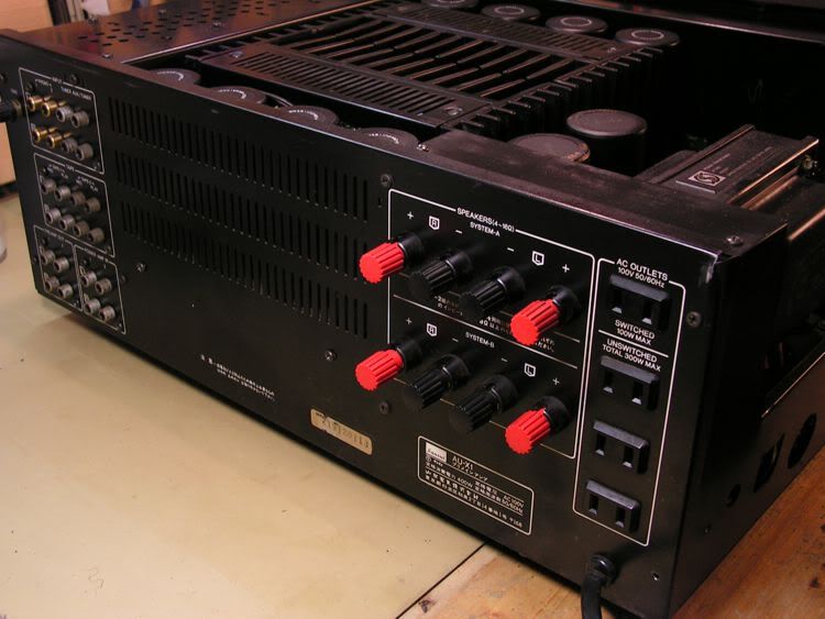
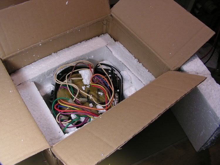
That amplifier I have bought in Japan directly, and it was for 100 V AC only. Because of that I asked the seller of that unit to remove main transformer, just only to reduce amplifier wight.

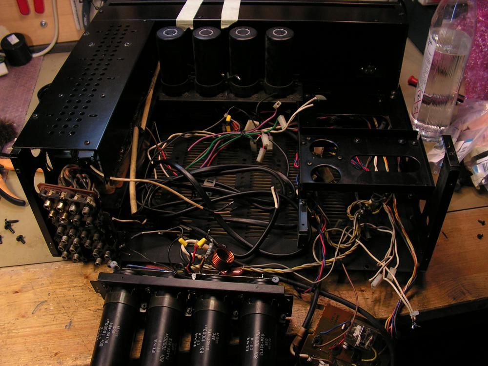
And here it is... on my bench

PICT4029.jpg


PICT4032.jpg


PICT4030.jpg


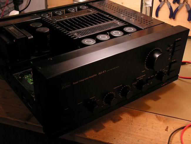
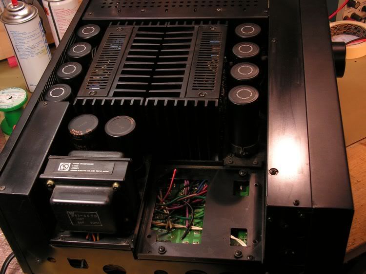
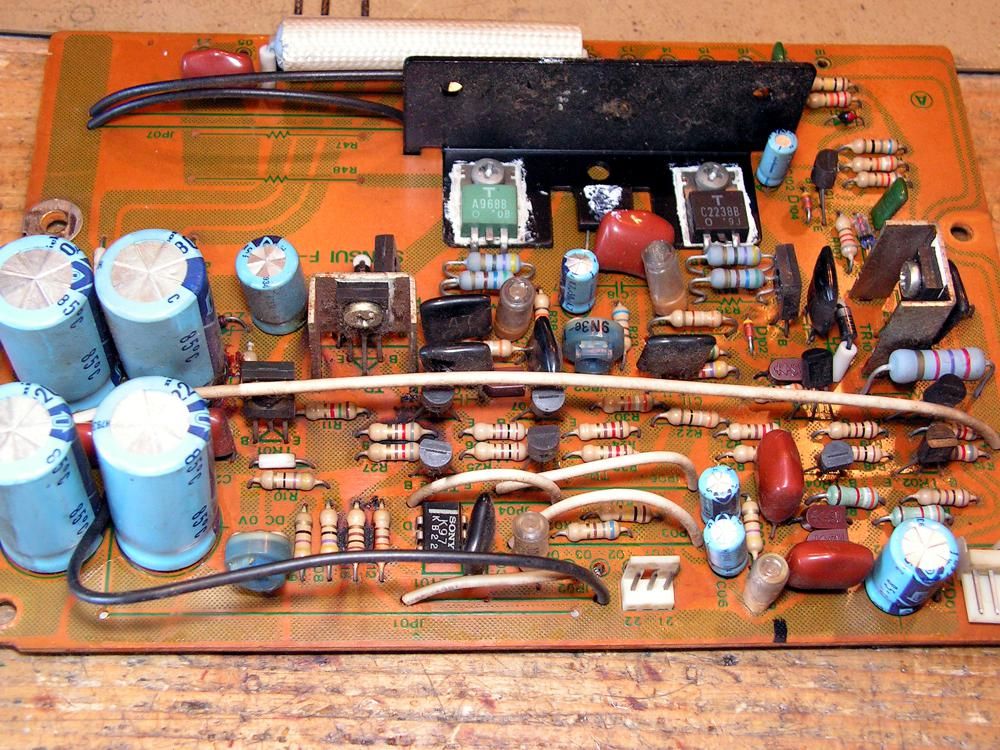
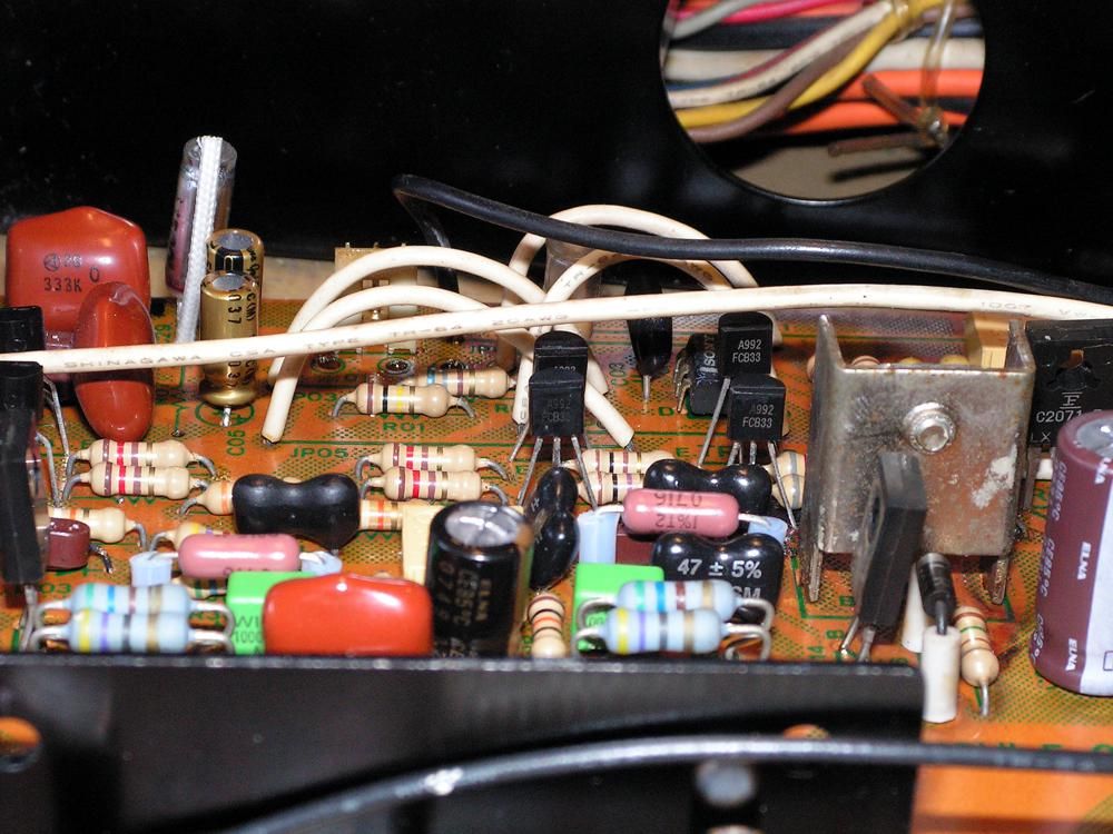
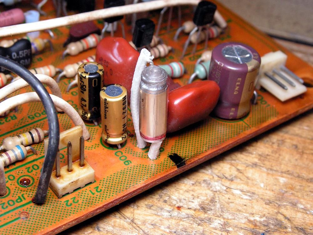
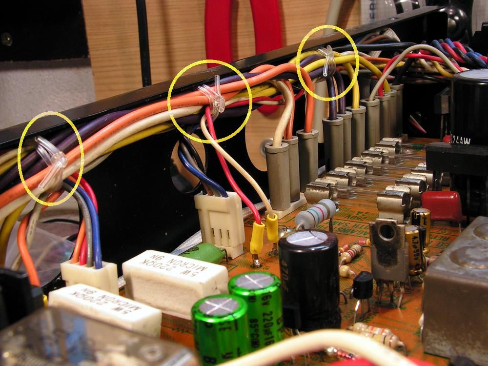
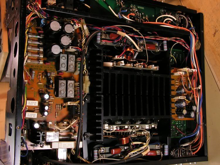
As you can see it is very clean outside, but inside it is very good too

PICT4033.jpg


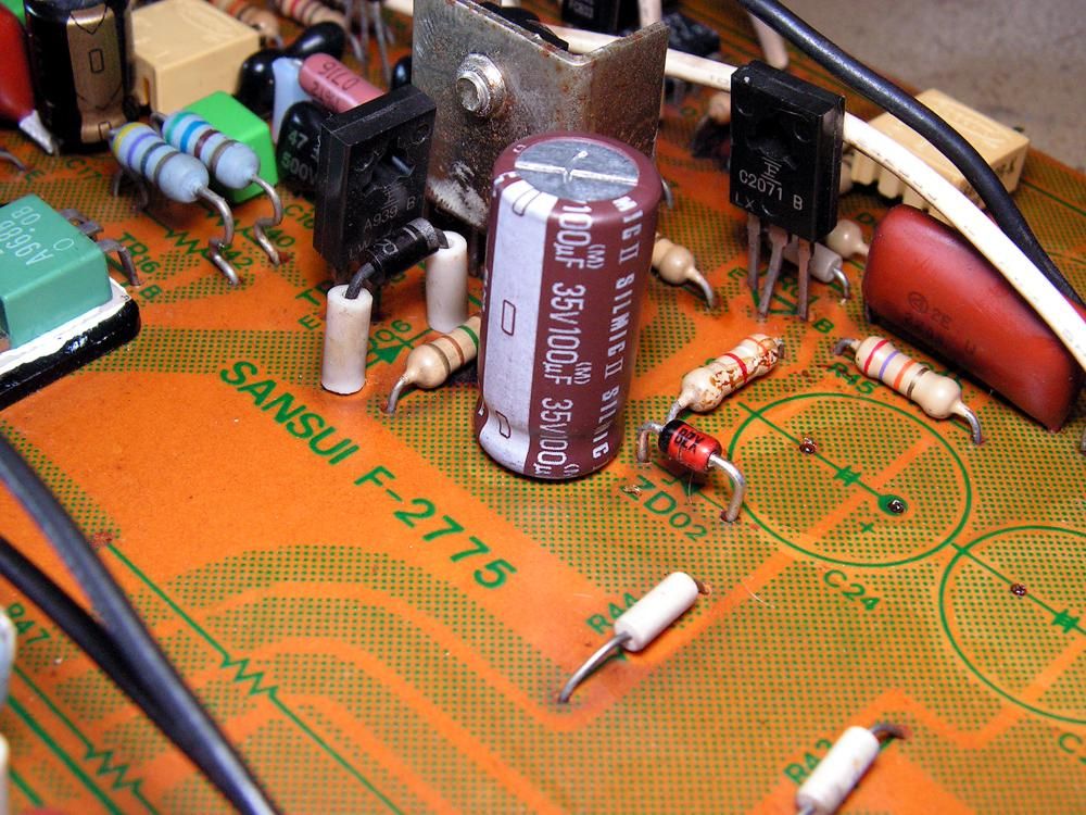
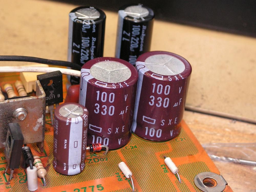
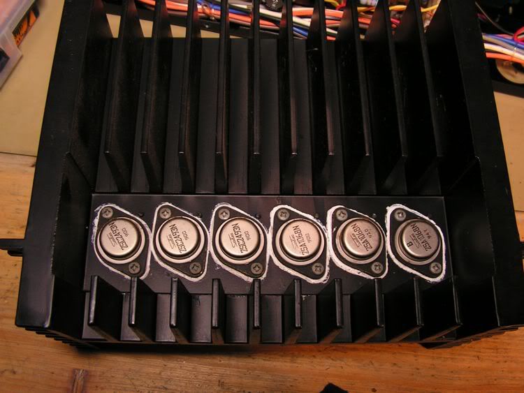
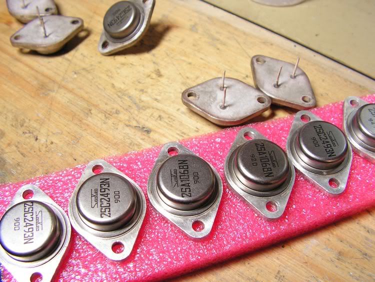
And the most important to me, it has genuine Sansui (made by Sanken) TO3 output transistors

PICT4049.jpg


PICT4052.jpg
 
Main transformer

So the next task was to find one genuine Sansui multivoltage transformer, and I have found one,
PICT4155.jpg


Unfortunately, that was not good... it had shorted primary winding :tears: so after so many days, I have found an another one :banana: and that was good!
So the restoration can be started!

But first... please take a look at the next picture, and tell me what is strange on that picture :D ?

PICT0618.jpg


Members of AK forum from Croatia cant participate at this quiz show :smoke:
 
I'll be back on that picture above later...

So the next step was to dismount the amplifier...

PICT0551.jpg
 
Far right hand emitter resistor....0.33 ohm, the rest are 0.47 ohm

PS.... looking forward to following this thread !!!
 
But first... please take a look at the next picture, and tell me what is strange on that picture :D ?

PICT0618.jpg


Members of AK forum from Croatia cant participate at this quiz show :smoke:

There seems to be one 0.33Ω emitter resistor and all the others are 0.47Ω....hmmm interesting.....:scratch2:
 
SUBSCRIBED! - Looking forward very much to seeing your full restoration of this rare Amp - :thmbsp:
 
Far right hand emitter resistor....0.33 ohm, the rest are 0.47 ohm

There seems to be one 0.33Ω emitter resistor and all the others are 0.47Ω....hmmm interesting.....:scratch2:

Yes! You're both right! That 0.33 ohm emiter resistor there is installed by mistake in the factory!!! And what is really strange at Service Manual all emitter resistors are 0.33 ohm ?!?!
 
Last edited:
0.33 Ohm emitter resistor

So I have to fix that... and what is good, I have an original NOS Micron 0.47 ohm 5W resistor...

PICT0619.jpg


and the result is here

PICT0620.jpg
 
But that was not only one problem here... here it is another one...

pict0615.jpg


That base 4.7 ohm resistor is so close to that screw, and it is really hard to unscrew it without damage that resistor, so I changed it on that way

PICT0616.jpg
 
I have changed the styroflex capacitors between plus and minus output stage power supply with polypropylene capacitor

PICT0617.jpg
 
RCA Connectors

Here I wish to say that really I cant understand why Sansui installed those RCA connector which are corrosion very sensitive ???
I have some of them NOS, so I changed those for AUX and Tuner input

PICT0553.jpg


Changing them is not some easy job, because you need to be very careful

PICT0554.jpg


And the result is here

PICT0559.jpg
 
Dual Cap 2200uf 100V

The next step was restoration those Dual Caps made by Nichicon

PICT0130.jpg


PICT0560.jpg


And the best capacitor for that was 2200uF 100V 105 C made by Kendeil

PICT0561.jpg


PICT0562.jpg


PICT0563.jpg


I covered the edge of capacitor case by heat-sink tubing

PICT0564.jpg


... and at the end, connected the wiring

PICT0567.jpg
 
Wow - great thread! The fantastic pictures are a real treat to someone like me who appreciates vintage stereo equipment, but doesn't know much about the internals.

Thanks for posting this information!
 
Driver Board

I'm back ....
OK, now it is time to see what we can do on the driver boards

PICT0579.jpg


and here it is one detail what I have done on that board

pict0598.jpg


multiturn trimmer, vishay dale rn60 metal film resistor, Elna Cerafine, silver mica, Vishay polypropylene instead styroflex capacitor

pict0599.jpg


deathly glue removed... zener changed...

pict0600.jpg


all small signal transistors replaced with the same model of today Fairchild Semiconductor production

PICT0601.jpg


replaced styroflex capacitor by the new one, but I didnt have radial type, so I installed axial type.

PICT0602.jpg


all solder points were resoldered, thermal grease replaced...

PICT0603.jpg


nut for fixing driver transistor soldered to the board for getting better connection (that nut connect collector of the transistor to the board)
 
Kale,
You are truly a master/Artist at restoring Sansui equipment. You are amazing my friend...Later Fever
 
Kale,
You are truly a master/Artist at restoring Sansui equipment. You are amazing my friend...Later Fever
Thank you my friend! But again, I must say you, yours AU111G is something what I would like to have only 15 minutes, just to listen one side of LP on that audio piece of gold :thmbsp:
 
On that driver board I made only one modification during that restoration; that board has four capacitors of 220uF at power supply circuit, but I decided to put close to power source two 330uF Nippon Chemicon (better filtration) and close to consumer circuit two 220uF Rubycon 220 ZL (speed).
All four capacitors are 105 degrees, because the board is located beside the heat sink.

PICT0611.jpg
 
I am really enjoying this thread, the pictures, and your commentary Kale. :thmbsp:

How you execute the work, and the decisions you make while doing it, are of great interest to me. :yes:
 
I am really enjoying this thread, the pictures, and your commentary Kale. :thmbsp:

How you execute the work, and the decisions you make while doing it, are of great interest to me. :yes:
Thank you John!

Finally, from that restoration I solved one big problem for me...
You probably already seen that Sansui fastened cables by some nylon tube, and I have searched all around the internet to find something similar, and finally I have found that :)

PICT0652.jpg
 
Kale - Like Hyperion - Am enjoying this thread too - Pix are superb!

Great job on the Dual Caps - BTW Is that a scorch mark under one of the four bottom row of resistors (first picture of the Driver board on post #14) - If it is, looks like some serious heat(?)
 
Back
Top Bottom