

tubesforever
Jim Howard
I am listing this information for those out there who own or contemplate the purchase of one of these gems. I thought this example might be fun to discuss with the forum.
This is an interesting study. You will see the bearing wear, a previous bandaid fix, and some pics of the motor assembly ou may never have seen before.
If you have questions please feel free to respond.
First off we should discuss the stock SP 10 mk II bearing.
The steel spindle is hardened and polished. It rotates within a bronze side wall bearing that is precision manufactured. The clearances on these bearings is very tight and in years of servicing these I have only had a few that were wasted.
This bearing design puts a button of self repairing plastic at the end of the shaft. This rides on a chrome steel ball that is a light press fit to the bearing shaft. Technics lists these bearings as low friction design.
Interestingly this thrust pad button rotates freely. Think about this a moment. When the friction between the ball and the button is higher than the button against the shaft you will suddenly be listening to a terribly noisy bearing.
With this particular bearing there was contact wear of the ball to the end cap holding the bearing in place. This means the ball which is a light press fit was also spinning against the cap. This indicates that the bearing was exhibiting unnaturally high friction.
I suspect it was run too dry. The lubricant left in the shaft resembled high temperature racing grease but in fact was the debris of the bearing mixed into the Technics oil.
Self repairing plastic has some hard components like glass or zirconium mixed in to help make the material tough. When this gets broken down during wear the material becomes an abrasive.
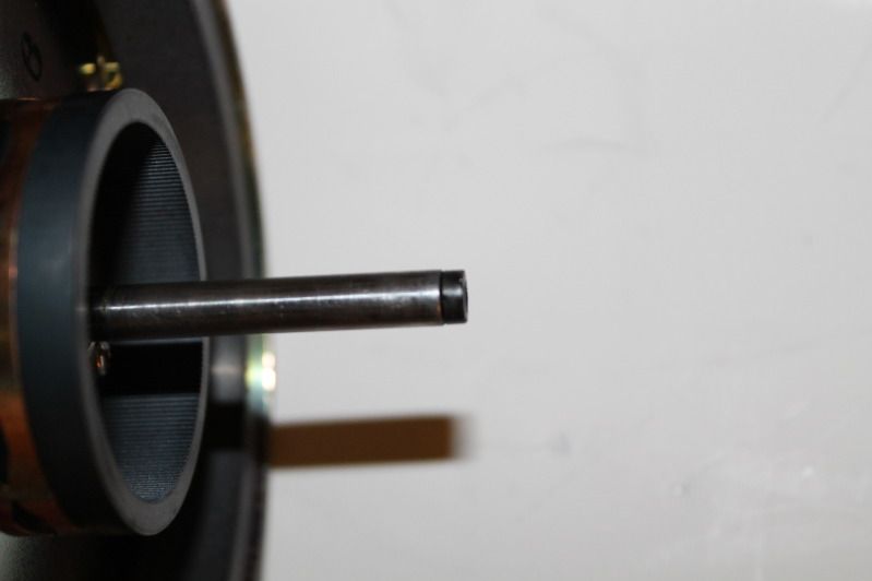
Notice the wear marks on the side of the bearing spindle shaft. Unfortunately the side wall bearing is also scored.
Picture one shows the bearing shaft and the self repairing plastic button.
The button itself shows about 0.60 thousands of an inch wear or about 1/3 to 1/2 of its usable thickness. However somewhere around 0.40 thousanths of an inch the top hat began to ride on the stator windings. This created enough noiset that the table was repaired before it shorted out the motor.
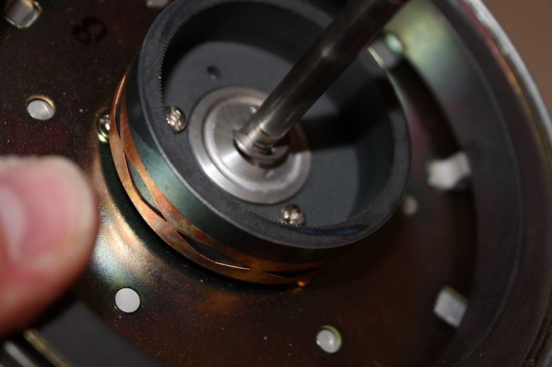
Picture two shows how someone pressed down the bearing 0.102 inches to get the hat off the motor stators. The overshoot was also an issue but we can discuss that later.
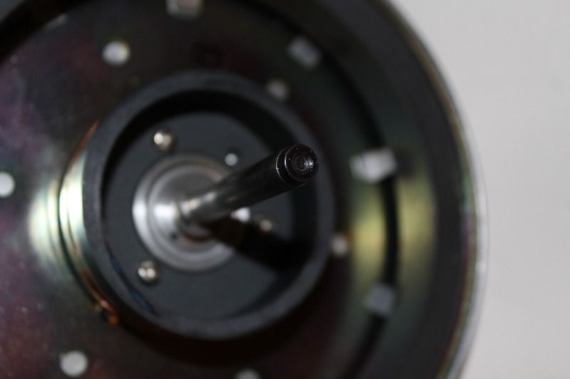
Picture three shows the wear on the stock bearing.
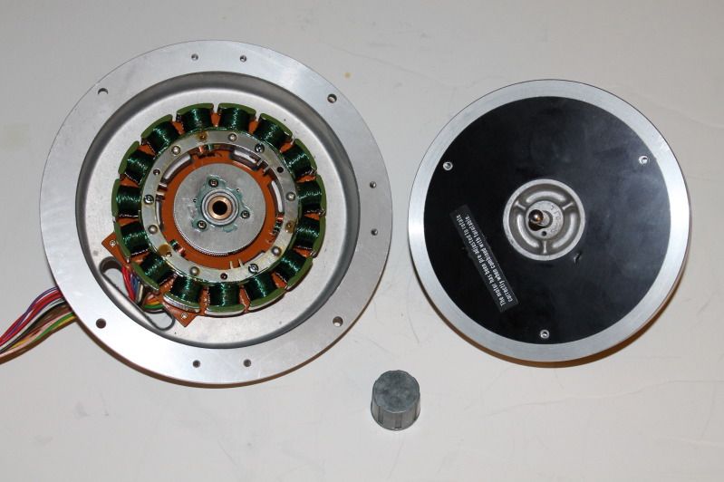
Picture four shows the motor windings. You probably cannot see it but the top of the windings showed transfer from the hat.
Enjoy the photos.
This is an interesting study. You will see the bearing wear, a previous bandaid fix, and some pics of the motor assembly ou may never have seen before.
If you have questions please feel free to respond.
First off we should discuss the stock SP 10 mk II bearing.
The steel spindle is hardened and polished. It rotates within a bronze side wall bearing that is precision manufactured. The clearances on these bearings is very tight and in years of servicing these I have only had a few that were wasted.
This bearing design puts a button of self repairing plastic at the end of the shaft. This rides on a chrome steel ball that is a light press fit to the bearing shaft. Technics lists these bearings as low friction design.
Interestingly this thrust pad button rotates freely. Think about this a moment. When the friction between the ball and the button is higher than the button against the shaft you will suddenly be listening to a terribly noisy bearing.
With this particular bearing there was contact wear of the ball to the end cap holding the bearing in place. This means the ball which is a light press fit was also spinning against the cap. This indicates that the bearing was exhibiting unnaturally high friction.
I suspect it was run too dry. The lubricant left in the shaft resembled high temperature racing grease but in fact was the debris of the bearing mixed into the Technics oil.
Self repairing plastic has some hard components like glass or zirconium mixed in to help make the material tough. When this gets broken down during wear the material becomes an abrasive.
Notice the wear marks on the side of the bearing spindle shaft. Unfortunately the side wall bearing is also scored.
Picture one shows the bearing shaft and the self repairing plastic button.
The button itself shows about 0.60 thousands of an inch wear or about 1/3 to 1/2 of its usable thickness. However somewhere around 0.40 thousanths of an inch the top hat began to ride on the stator windings. This created enough noiset that the table was repaired before it shorted out the motor.
Picture two shows how someone pressed down the bearing 0.102 inches to get the hat off the motor stators. The overshoot was also an issue but we can discuss that later.
Picture three shows the wear on the stock bearing.
Picture four shows the motor windings. You probably cannot see it but the top of the windings showed transfer from the hat.
Enjoy the photos.


