

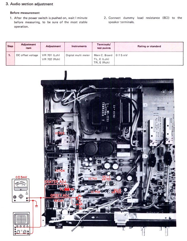
Can someone please help me understand what's being said here? Are these instructions (from a Yamaha CR-640 service manual) for adjusting what are usually called the DC offset and the bias? And is this saying you can use either a DMM or an O-scope? Also, I'm confused by the terminology "center adj" and "offset adj." Is what's called "center adj" here what's usually called DC offset? And is the "offset adj" the bias? (scratches head)
I checked between both TL1/TL2 and ground and was able to pretty much zero them both out (via VR701/702). The other test points (E for both sets: E-left and E-right, I assume) would pretty much require removing the bottom cover, since the insulation on those wires is trimmed right at the board with zero, exposed, bare wire. So do I measure between each E point and ground and use the same trim pots to shoot for 0 +/- 5mV (or how exactly do I adjust this one)?
I checked between both TL1/TL2 and ground and was able to pretty much zero them both out (via VR701/702). The other test points (E for both sets: E-left and E-right, I assume) would pretty much require removing the bottom cover, since the insulation on those wires is trimmed right at the board with zero, exposed, bare wire. So do I measure between each E point and ground and use the same trim pots to shoot for 0 +/- 5mV (or how exactly do I adjust this one)?