Denon PRA-1000 Repair

mccuskerkt

AK Subscriber
Subscriber
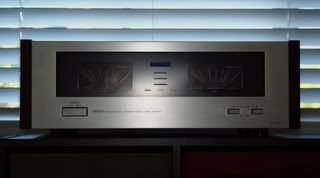
I recently acquired a champagne-colored Denon PRA-1000 pre-amp and POA-1500 amp. They really are good-looking units featuring a clean and uncluttered design. Denon designed these units before manufacturers began producing button-heavy rigs representative of the eighties. After unpacking, connecting, and admiring the pre-amp and amp combo, I pressed the amp’s power switch and watched in silent reverence while the built-in-test carried out its required duties and informed me of its completion by illuminating the massive power meters. Next, I pressed the power button on the pre-amp, and almost instantly, the amp's thermal protection light illuminated. The amber light raised alarm and my heart sank. Tonight my personal quest for faithful musical reproduction would reach no new territory, no meters swaying to guitars, drums, and passionate voice. Tonight, I will be admiring these amps silently, and with these photos, I invite you to do the same.

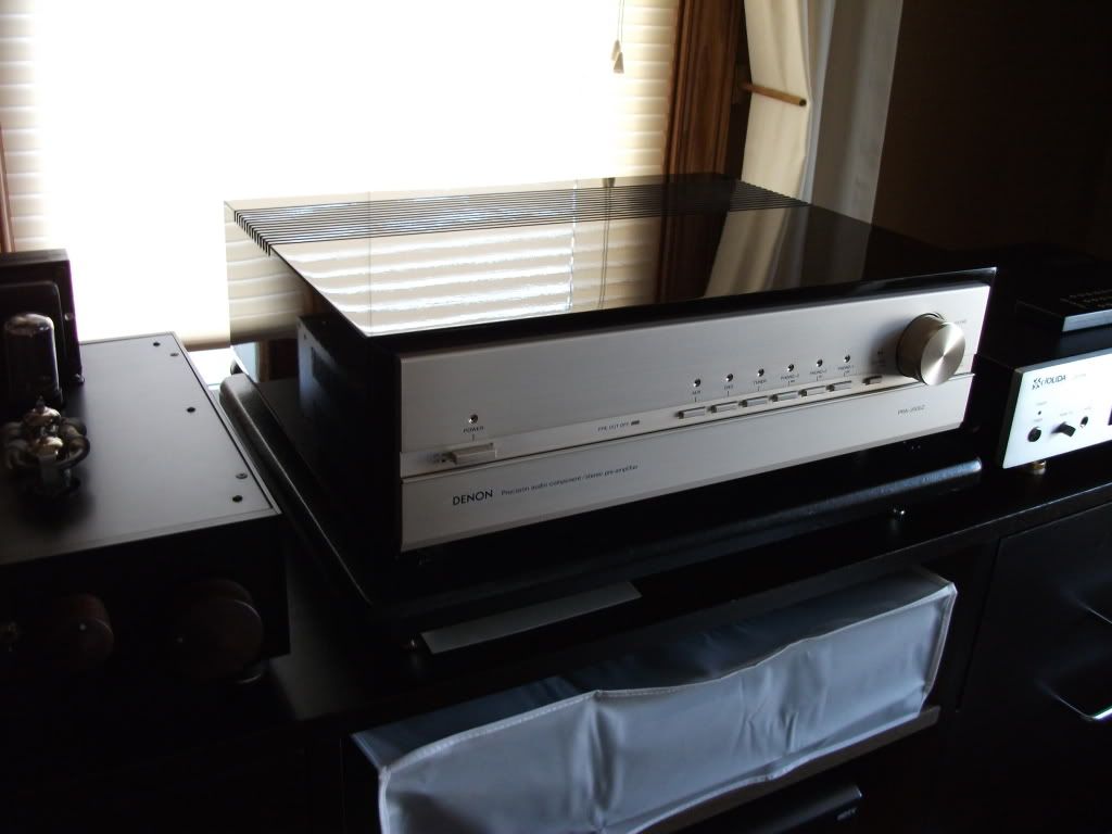
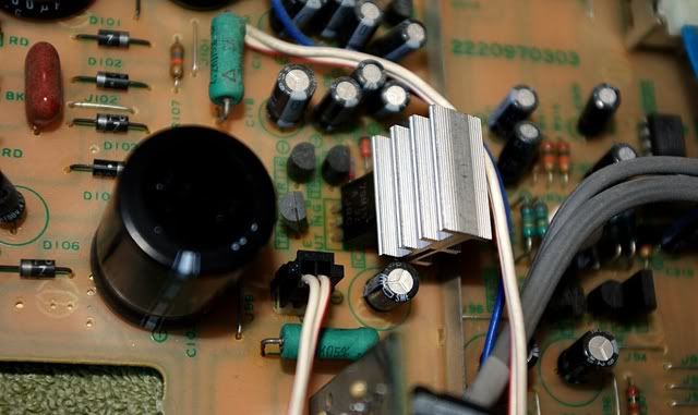
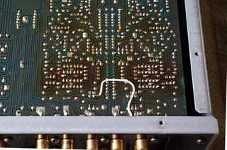
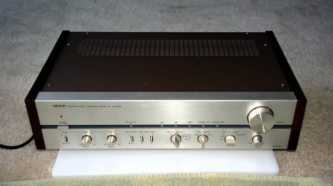
Here is the pre-amp:
PRA-1000FrontTop.jpg
 

Attachments

  • PRA-1000FrontTop.jpg
    PRA-1000FrontTop.jpg
    28.8 KB · Views: 46
Last edited:
Opened Up

I am a veteran of the United States Marine Corps; my job was to repair field communication equipment. I spent many hours fixing radios, computers, and occasionally, Marines’ personal IPods and laptops. While deployed to a combat zone, these items are essential for a Marine’s battle against both enemies present in every war: bad people and boredom. I was disappointed after I discovered that the PRA-1000 was defective, but then I became excited at the prospect of opening up the pre-amp and figuring out what the problem might be. Fixing electronic devices is something of a “zazen”; it is a needed release from the day’s stresses and a reminder of my past. I hope you will join me as I repair and restore this well-regarded pre-amp.


Pre-amp’s insides before any alterations are made.

PRA-1000TopUncovered.jpg


A little progress that I made while cleaning decades of oxidation residing on the main circuit board (I could not get everything completely clean using alcohol and q-tips, does anybody have any good methods for more detailed cleaning?):

PRA-1000BottomResidueCleaningProgress.jpg


A cracked solder joint on IC102 from the bottom of the board:

PRA-1000BottomCrackedSolderJoint.jpg


Same component viewed from the top

PRA-1000TopCrackedSolderJoint.jpg


A wire that needs replacing:

PRA-1000BottomUncoveredWhiteWireClose.jpg
 
Last edited:
I'd go further and reflow every solder joint you can get to, just to get that out of the way. Old solder doesn't always have an obvious failure. I find that big flexy boards with heavy unsupported parts will have suspect solder, as that is all that is keeping the part in place.
Good luck with your Denon gear, that's some nice stuff!
 
Nice story about you! Very interesting read for sure. :) I hope you get the pre amp running. It looks very nice and Denon gear used to be fantastic around this era. Do you have any pictures of the main amp? The mention of those big power meters sure has me intrigued. :)
 
Just curious. You say you turned on the amplifier first, and then the preamp, and then the amp went into protection?

It's always a rule to turn on the preamp first, then the power amp. Could this have caused your problem?

I once fried a power amplifier (shorted one output transister per channel) by the resulting preamp turn-on thump by turning on the power amplifier first, then the preamp.
 
Last edited:
@ryuuoh,
Thanks for the great idea! This certainly is a big flexy board with no support other than where it is bolted onto the front and rear of the chassis, and I suspect that more than a few of the solder joints are defective or close to failure.

@Ruxman,
Thanks! I enjoy writing almost as much as I enjoy music and audio equipment; it is a wonder why I did not do this earlier. I do not have any photos of the amp yet, but I will gladly post some this evening.

@Century Tek,
I did not consider the possibility of damaging anything by powering everything up in that order (power then pre), and I will certainly take your advice every time I power these units up. I employed the "pop-and-swap" troubleshooting method, connected the pre-outs of my home theater receiver to test the amp (works!), and connected the pre-amp to a cheapo amp, which immediately went into protection mode. After visually inspecting the pre-amp, I suspect that the cracked solder joint on IC102 is the problem. It will be interesting to see if the bad solder joint has caused any other problems.

I really appreciate everybody feedback and comments. Audiokarma really is an awesome place for “nerds”! I cannot wait to get home from my day job and get to work on this pre-amp.
 
First..Thanks for your "outstanding" service to our country. Semper Fi Marine:thmbsp:
 
As promised, here is a shot of the POA-1500. The glass has been pushed out and will need to be re-glued, otherwise the amp is in really good condition. I read on another thread in this forum that the Nippon beer-can caps have a tendency to leak and I have not checked yet, however the amp sounded superb when hooked to my Denon 3806 and driving my Martin Logan Motion4 fronts.

POA-1500FrontwoGlass.jpg
 
mccuskerkt,I wish you the best getting the Denon up and running.The phonostages in these lines of Denon gear are nothing short of amazing.I ended up selling some highly regarded stand-alone phonostages shortly after the Denon PRA-2000z was put into use.
OMR

Denon001.jpg
 
@avionic
I greatly appreciate your gratitude. Thank you for your twenty years of service as well! My wife and I grew up in Iowa, she in Manchester and me in Ryan.

@OldManRiver,
That pre-amp is gorgeous! Denon puts doors to good use in their designs. I am anxious to run my AR XA turntable through the PRA-1000's phono section, although I have a sneaking suspicion that your PRA-2000z has a better phono section than my pre-amp.
 
Last edited:
It is worse than I expected. I removed IC102, which is a negative voltage regulator, and noticed that the copper that the solder would fuse with is gone. I do not know how to get around this. Does anybody have any suggestions?

PRA-1000IC102Removed.jpg
 
perhaps some little copper washers, slipped down over
the leads, that would allow for soldering both the leads and also reach out to the traces?

probably should use a clip to heat sink the leads as you solder, the washer unless very thin will take a bit more heat
to get a good solder flow.

bob g
 
I usually just sand away a bit of the appropriate varnish over the trace feeding that leg, fold over the pin onto the bare copper, and solder.

I have the PRA-1500 on my main system, a top notch preamp, dead quiet.
 
Put a new voltage regulator in there, and then bend the legs so that they reach out to the other solder pads near the holes. Then solder the bent edges on there.

I can see that there is one solder spot near every hole, so the procedure will not be a problem.
 
@denon bob, lukiedog and Ruxman:
Thank you for the suggestions, I will probably sand away some of the nearby varnish to expose the traces and solder on to the exposed copper. I feel this will look the cleanest.

@Ruxman,
I am curious, why do you recommend that I use a new voltage regulator? I understand that the one I have is 30 years old, but if it tests ok why would I want to replace it?
 
You need some lead length to do what we are talking about, the existing one, leads have been clipped. You may also want to put a dab of hot glue to help support the component, as all three of the "rings" have been compromised and there is nothing for rigid support.
 
Another technique is to drill new holes through well adhered trace, sand the varnish off of them, and use those for the legs of the component. You need space for the legs and they won't be all nicely lined up, but all askew. You can of course, do both, some legs folded onto sanded trace, others drilled through. The drill through provides good support for the component.
 
This is my initial plan for the voltage-regulator lead layout. There is not much copper left on the right-most trace, so I will try to avoid removing what little is left by removing varnish and bending leads instead of drilling a new hole. I will use a carefully placed bead of hot glue to help support the heavy regulator chip and heat sink. I have to find a suitable replacement regulator, but I have the service manual so it should not be difficult. I truly appreciate all the advice and support I have received.

PRA-1000IC102RemovedSolderPlan.jpg


In a related story, today I learned that while working on a military base (Camp Pendleton) and using their network, you should not follow links to Chinese manufacturers who host their website on servers located in China. I had to have a little chat with the Network Admin… Oops!
 
Your planned approach looks sound. If you could find a way to support the part on the other side of the board, it would probably last forever.
BTW, I had to repair lost solder pads on my Sansui 9090 driver board. I removed the solder mask and made "pads" out of short lengths of solid copper wire by bending them around the legs of the old part.
 
Back
Top Bottom