Dynaco Mark 3 rebuild questions and problems

kwingylee

Well-Known Member
All:
I embarked on rebuilding my Dynaco Mark 3's that I purchased a few months ago. One worked perfectly and the other one worked intermittently.

I began worked on the one that was intermittent. I have replaced all of the power supply and coupling caps.

I have also began replacing the resistors in the circuit board and the ones beneath the chasis. I found one resistor that drifted way off.

However, I found some anomalies.

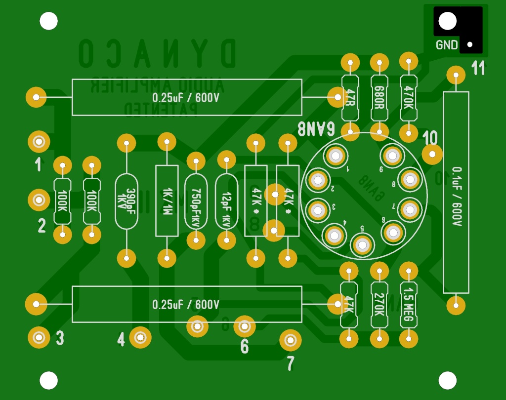
1. I cant ascertain the value of the part that is directly to the right of the 1K OHM resistor (left of the AN8 tube). Can someone enlighten me on it?
2. I cant locate the rectifier diode as shown in the schedmatic. Also, some schematic show a 1K resistor to the anode side of the diode while other show 4.7K. Which one is more current?
3. Finally, the amps came with 3A slow blo fuse. The fuse blew after I played music on the amp (post mod) for awhile. There is nothing but a switch on the primary side. What gives?
4. I was to keep the original boards as design by Hafler. Which set of resistors require close matching?
5. FInally I am putting in metal film resistors vs carbon film resistors... any issues with that?

Any help will appreciated.

Kwing
 
Post some pics of the underside concerning the diode. Maybe some mods have already been applied.

Here's a layout diagram.

mark_i16.jpg
 
Last edited:
OK, I found the answers to 1 and 3. If anyone can help with the fuse blowing problem and the location of the rectifier, that would be great.

1. Its a 750pf cap
3. The 47K and the 100K resistors need to be matched. Leave the 11.2 ohm resistor alone.
 
Regarding the bias rectifier, the version with the 1000 ohm resistor is the older version that used a selenium rectifier to produce the negative bias voltage. In the newer version, they switched to using a silicon rectifier, requiring the 1000 ohm resistor to be increased to 4700 ohms.

I hope this helps!

Dave
 
Thanks Rick and Dave... I am going to replace the selenium rectifier with a IN4007 today and swap to the 1K with a 4.7K and see if that fixes it... and the board layout definitely helps.

If that does not fix it, I will post some pictures.

Happy New Year!!
 
I have spent the last few days trying to bring one of my monoblocks back to life. I have ran into a number of serious issues.
I have replaced all of the passive device on the original driver board, except the 750pF cap.
All resistors were matched to the exact values in the schematic.
The 390pF and 12pF caps replaced with 383pF and 10pF caps respectively.
The Germanium rectifier replaced with 1N4007 and the 1K resistor increase to 4.7K.
The 6.8K rail resistor was way off and was replaced.
The 11.2 ohm bias resistor measured perfectly and was left untouched.
The 4.7K ohm resistor in the bias network was replaced.
The 10K bias POT measured ok and was left it the circuit.
The 18K ohm resistor in the bias network drifted to around 20K, I did not replace this.

1. The amps play music but blows the 3A fuse after sometime...
2. The bias voltage is way high... well in excess of the recommended 1.56Vdc
3. The B+ voltage is 1/2 the value of what in should be.. less than 250Vdc.. with the output transformer out of the circuit.. I measured over 500V.

I believe I have checked all of the connections and they look good. I can't see the problem. Maybe I am tire of looking at this thing.

The next step is to start removing the new parts. Maybe something got blown in the process... I appreciate it if some of you more seasoned builders can give me some advice and save me sometime....
 
Last edited:
Here are some pictures of what I have.
 

Attachments

  • IMG_1391[1].jpg
    IMG_1391[1].jpg
    110.1 KB · Views: 99
  • IMG_1393[1].jpg
    IMG_1393[1].jpg
    100.7 KB · Views: 73
  • IMG_1394[1].jpg
    IMG_1394[1].jpg
    96.5 KB · Views: 69
  • IMG_1395[1].jpg
    IMG_1395[1].jpg
    104.6 KB · Views: 67
  • IMG_1398[1].jpg
    IMG_1398[1].jpg
    77.2 KB · Views: 90
After a few hours spent checking and probing voltages, I finally found the problem to the amplifier. I inadvertently reverse the polarity on the 50uF cap to one leg of the biasing pot. This pulled down the voltages to the grids of the KT88s to a mere -8V and causing the low B+ and high dc bias across the 11.2 ohm resistor.

Replacing the capacitor solved most of the amps problems. B+ is at 475V (vs 210V) and the voltages at the control grids are set to -55V (was -16V). However, when I measured the voltage across the 11.2 ohm resistor, its only reading about 0.8Vdc.

What gives???
 
If the voltage reading across the 11.2 ohm resistor is only .8 vdc, then one possibility is that one output tube is not conducting any current, so check the wiring of these tubes carefully, and make sure the OPT has continuity from the primary CT (B+) lead to each screen (pin #4) and plate (pin #3) lead.

Assuming all is good with the transformer, try removing each output tube one at a time, and see if the reading changes. If you remove one tube and the current reading does not change, then either that tube is bad, or the wiring to it is incorrect.

If the 11.2 ohm resistor is accurate, the target voltage produced across it (1.56 vdc) is the important voltage to achieve -- not specifically -55 volts on the grids. The grid voltage is a typical voltage based on typical tubes, but not a precise voltage. If it only takes -52 volts, or as much as -58 volts, that is of little concern, and results from the tolerances of manufacturing vacuum tubes. The important point is achieving the 1.56 volts across the 11.2 ohm resistor.

I hope this helps!

Dave
 
Dave:
I believe I was able to adjust the bias pot to get 1.56Vdc across pins 1 and 8. However when that was done, I only measured about -20V at the grids. I then adjusted the pot to get -55V at pin 5 (I think), which resulted in the 0.8V.

I will double check these measurements as I may have measured the 20V on the other side of the 1K resistor pairs...(spots 1, 2 and 3 on the PCB). It was late.

Thanks for the helpful suggestions....
 
This is acting like there is very low B+ voltage, but that would only be true if both output tubes are in fact conducting current. Therefore, we still need to know this point for a fact. The easiest way to determine this is to do the test I mentioned previously of seeing what happens to the pin# 8 voltage when one tube is removed at a time.

This will either come down to very low B+ voltage, or one tube not conducting. You can measure the B+ with your meter, while pulling a tube will tell you which tube (if either) is not conducting any current.

Dave
 
Dave:
Just made more tests.
AMP is running off a variac set to 110Vac or so.
With the original tubes in place (samples 1 and 2), I was only able to reach 1.2Vdc at pin 8 with the pot turned fully clockwise.
I then parallel a 47K resistor with the 18K (actually measured 20K) ohm resistor and I was able to set the bias at pin 8 to 1.56V with the POT turned fully clockwise.

I then performed the tests you suggested put in ONE KT88 at a time. While measuring the voltage at pin 8. All measurements done with the 47K paralleled with the 18K.

Sample 1 only 1.45Vdc
Sample 2 only 1.215 Vdc
Sample 3 only 1.44Vdc
Sample 4 only 1.22 Vdc

I put in Samples 2 & 4 together. The highest voltage I read on pin 8 is 1.44Vdc with the POT turned fully clockwise.
I did similar tests with samples 1 & 3 together. This combination gave me over 1.6Vdc at pin 8. I was able to reach 1.56V by turning the POT counterclockwise a bit. In this position, I measured -40V at both pin 5 s with no input signal applied.
The results with Samples 1 & 2 are already reported above.

Maybe I need new KT88s??
 
The Dynaco was designed to operate from 117 vac, so that is certainly part of the problem. Low AC voltage produces lower B+ voltages, and also (for some tubes) does not allow the heaters to reach their designed operating temps -- both of which work to reduce current flow through the tubes.

Since it has now been shown that both tubes are conducting, I would attempt to bias the unit normally using a 117 vac line voltage, and see if that doesn't bring the bias control back to a more centered position when producing the target Biaset voltage.

Let us know!

Dave
 
If your plate and screen voltages are where they belong, but it requires significantly less bias than spec (closer to zero) to get proper current flow through the resistor, it sounds like your tubes are tired. The plate and screen voltages need to be confirmed first though, and it wouldn't be a terrible idea to make sure the heater string is producing at least 6.0 volts. Low heater voltage will tend to make the tubes conduct poorly, especially if they are heading towards being weak anyway.
 
I checked the AC bias voltages in my updated sample and they read 6.3Vac.
I then made more measurements today of both amps and compared them with ones posted by rpampt and his thread. His line voltage is 127V, I run both amps off a variac set to 117V.


XXXXXXXXXX| w KT88 samples 1&3 | w KT88 samples2&4
6AN8 rpampt | my updated mk3 xxx | my unchanged mk3
-----------------------------------------------------------------
pin 1 | 373.5V | 302V | 281V
pin 3 | 119.5V | 133V | 137V
pin 6 | 100V | 123V | 129V
pin 7 | 37.5V | 54V | 26.3V
pin 8 | 1.062V | 0V | 0V
pin 9 | 1.08V | 0.85V | 0.8V

Test points
4 xxxxx 516V 462V 455V
5 xxxxx 492V 435V 423V
6 xxxxx 418V 381V 357V

KT88
3 xxxxxx 483/486 457 450
4 xxxxxx 488/488 461 452
5/6 xxxx -52.5 -51 -45
1/8 xxxx 1.56 1.56

GZ34
2 xxxxx 498 472 493
4 xxxxx 409Vdc 425Vac 420Vac
6 xxxxx 410Vdc 425Vac 420Vac
8 xxxxx 499 472 493

Shortly after this the GZ34 in the unmodded sample blew.... now I need recommendations on which of the new GZ34 variants to buy: Sovtek? Ruby? NOS? Used Mullard... Can I plug in 5U4B (I have a few of these)...instead?

In looking through my old tubes, I found a set of RUBY KT88s from a AES SuperAMP DJH that I used to have. So I will to throw those in there too...
 
Last edited:
I'm not following everything too well, but looking at your pictures, it appears there is a green wire running from pin 8 on the rectifier to somewhere by pin 2 or 3 of the KT 88 closest to the rectifier. It may not attach there, but it looks like it does. That doesn't look right to me. Where is that wire going?
 
a 5U4GB will draw more current than a 5AR4 does. Not sure if the transformer can handle that, folks that know Dynaco gear better can answer that. They are also directly heated, so the voltage comes up quicker. If you have any caps that aren't properly rated, they'll see 50-100 volts higher than normal for a few seconds on powerup. Marginal ones will probably fail.
 
I'm not following everything too well, but looking at your pictures, it appears there is a green wire running from pin 8 on the rectifier to somewhere by pin 2 or 3 of the KT 88 closest to the rectifier. It may not attach there, but it looks like it does. That doesn't look right to me. Where is that wire going?

Rick:
Thanks for look at my pictures. Your threads inspired me to go down this path.... I am sure I will ask you about your upgrades once my monoblocks are updated, especially the individual biasing part as addressed in your latest thread.


U are absolutely correct as the rectifier pin 8 should go to the choke and should not go to the KT88 at all. I will have to check that this weekend - as I am back at work this week. What I hope to get done in a day is taking me almost a week..
 
a 5U4GB will draw more current than a 5AR4 does. Not sure if the transformer can handle that, folks that know Dynaco gear better can answer that. They are also directly heated, so the voltage comes up quicker. If you have any caps that aren't properly rated, they'll see 50-100 volts higher than normal for a few seconds on powerup. Marginal ones will probably fail.

After going through various forums, I decided to stay with the GZ34. 5U4 substitution is not encouraged in the Mark 3 manual - even though it is allowed in the ST70.

I ordered a set of SOVTEK GZ34s and a pair of plugged in SS rectifiers off ebay. I will try them this weekend. The SS rectifiers work for 5U4s and GZ34s and provide a simple and safe means to hear the differences between tube and SS rectification. They will replace the AMPEREX GZ34s that I have currently.

The MULLARDS are way out of sight. A pair of those costs almost as much as what I paid for the amps.....
 
The SS diode Mod on the tubes4hifi website Forum can help the tube rectifier last without hurting sonics or affecting the slow warm up the GZ34/5AR4 is famous for. UF4007 are a newer faster & quieter diode for a few cents more.

This Mod does not replace the tube but assists and helps protect it making it last as new production are weaker than NOS. They are just using unused tube pins to mount the diodes.

You can also wire the diodes in series on the secondary B+ wires right to pins 4 & 6 of the tube rectifier. Just make sure the band end of the diode is at the tube socket , plus use heat shrink tubing for support and insulation.

http://dynacotubeaudio.forumotion.com/t1006-tube-rectifier-diode-mod
 
Back
Top Bottom