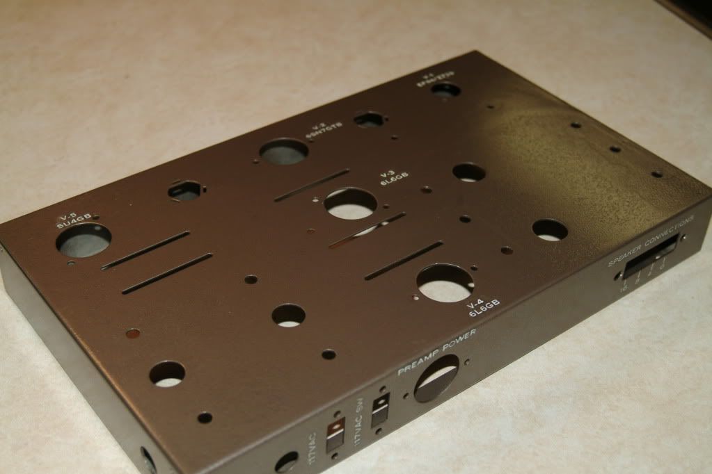
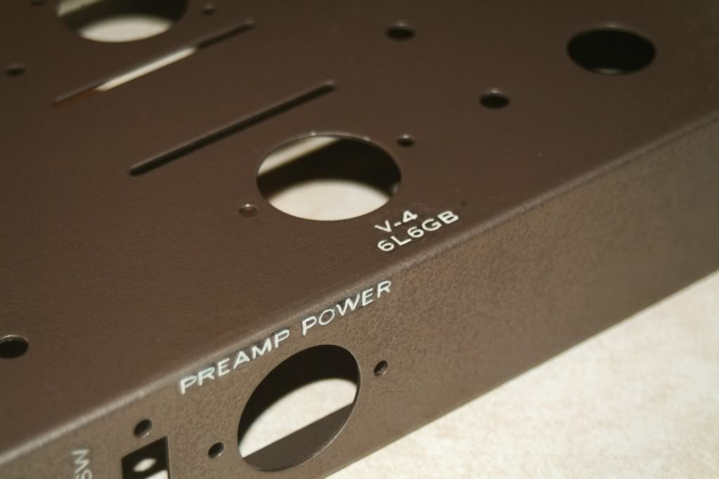
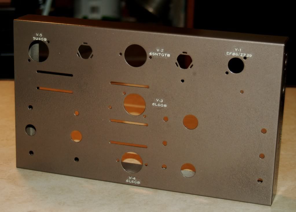
Eico HF-22's total reassembly.

Only problem with converting them to HF-35 is that you'd have to get different power transformers. And there are folks who say that even with less power, the HF-22 amps sound nicer than the HF-35.

I'm one of those.

IMHO, the Eico 32004 output transformer is a GREAT 6L6 transformer, but only a so-so EL34 transformer. Asking the additional power output from it definitely seems to degrade its bass performance (it will do full 20-20K Hz bandwidth at extremely low distortion at 22w, but starts to saturate a bit at 20Hz at 35w- in fact, at anything above about 27w).

The one experiment I'd maybe want to try with EL34s in a HF22 chassis, would be to run the 32004s as non-ultralinear (just disconnect the UL taps and ignore them), and run a pair of EL34s in fixed-bias pentode mode. Use the 16 ohm tap for 8 ohm speakers, and the 8 ohm tap for 4 ohm speakers, to create about a 3800 ohm primary load (instead of 7600 ohms). The combination of needing less idle current this way, and the evidence provided that sometimes running transformers at half their rated impedance (as Steve L. and David G. posted about recently) can lead to surprising performance at high output levels... this might work.

Regards,
Gordon.
 
Last edited:
"Ray had repaired the bad smoothing problem using an 8μF tubular capacitor in place of the faulty cap. Although the replacement was rated at 450V and the HT only around 250V, that didn't help. For his efforts he now got a strongly worded lecture on the ripple current rating[1] of electrolytic capacitors, ending with the stern admonition: NEVER - EVER - FIT - A - TUBULAR - ELECTROLYTIC - FOR - MAIN - SMOOTHING - EVER - AGAIN!"

What year was this?

I ask, as I've liberally used even what would be called "cheap" electrolytic "tubular" caps for power supplies, and never had even a minor episode remotely similar to this.

Also, companies such as Stromberg-Carlson and Heathkit used these "tubular" caps, themselves, as power supply caps. Never an issue there...

Also, I've seen many table radios, phonographs and such from the 1950s, with tubular caps AS main supply caps. Even on half-wave rectifiers! And with no evidence of explosion. Sure, they needed to be changed out due to 50 years of electrolyte degradation... but they lived long enough for me to see them in recent times!

I think that the episode above, may have just been caused by a sub-standard provider of "tubular" caps... or, a situation where ridiculously high ripple currents existed (i.e, too much load on not enough cap)... or the cap was polarized backwards...

Regards,
Gordon.
 
Ohighway,
I looked into those when I restored my Fisher 800c. I opted for a pair of cans instead. The Fisher was in primo condition, so putting something nice on it was an easy call..

I see you have a pair of Fishers. I'd like to see them. And I'm guessing that you're using the Yamaha C-45 as the preamp?

I fully understand what you're saying, and on a piece as wonderful as your Fisher I'd certainly pony up the extra $$ to have it running and looking -perfect-.

On your Eico amps? Using other caps doesn't have to make them ugly. Just electrically disconnect the can caps but leave them in place. (Hell, polish up the cans a bit while you're at it) Install new caps of your choice under the chassis. Hope you can get that one chassis welded and that dent out of it. I'll say this just one more time, then shut up. They would look GREAT if you strip and repaint them. You're going all new with components, why not cosmetics too? It's not like these are pristine survivors that should be preserved as such....

Oh, my 50A amps can be seen here. Ditto the black plastic crapstack which includes the C-45 preamp.

http://www.audiokarma.org/forums/showthread.php?t=355157
 
What year was this?

Thanks for this reassurance, Gordon. The comment was made earlier this year, but more importantly the story relates to an event 50 years ago!

The point came up when the writer, who is a retired EE with lots of tube circuit experience, was discussing PS caps for the restoration of a home-built Mullard 5-20 that had been converted to solid state rectification. In my rebuild I reverted to a GZ34 and installed Dubilier PIO caps.

Martin, it sounds like you are good to go with the mouser part caps you listed. You'll just have to find something to cover the can holes in the chassis.
 
Martin, it sounds like you are good to go with the mouser part caps you listed. You'll just have to find something to cover the can holes in the chassis.


As mentioned, one of the best ways to plug up that chassis hole is to just electrically disconnect the can cap and leave it there.

BTW, what's a 'budgie' ?
 
Dandy,
I guess I've got three options on the cans...bypass the cans on top and just wire up the caps below, restuff the cans-which would be a first for me or if I botch the restuff, I can always purchase some new cans. :yes:
But I'll take your advice and look for some beefier caps.
I did like the story though...bits of silver foil on the inside and bits of grey budgie crap on the outside! :D

Babblefish,
Thanks for the nod on the 800c.
If you haven't already, take a look at a early 60's RadioShack catalog.
Talk about drooling.
http://www.radioshackcatalogs.com/catalogs/1960/

GordonW,
I was hoping you would show up somewhere along the way. While researching the HF-22's I came across a number of your postings. I can tell you really like the HF-22. Your insights here will be much appreciated.
Gordon, before I order parts, are there any component upgrades that you know of to improve the HF-22's sound?

Great room and set up Rick...those Fishers are awesome!
Google budgie...I did!

Thanks guys.
Martin
 
I didn't mention using your old can caps because I didn't see any in your pics.

The pic is for Rick. (What a great room you have for listening.)
 

Attachments

  • 5625591-yellow-budgie-sits-on-a-cage.jpg
    5625591-yellow-budgie-sits-on-a-cage.jpg
    50.1 KB · Views: 30
GordonW,
I was hoping you would show up somewhere along the way. While researching the HF-22's I came across a number of your postings. I can tell you really like the HF-22. Your insights here will be much appreciated.
Gordon, before I order parts, are there any component upgrades that you know of to improve the HF-22's sound?

I upped the value of the cathode bypass cap on the outputs (I think I roughly doubled it, IIRC?), and the same for the power supply cap values (about double, except for the one directly connected to the rectifier tube- I think I only used 47uf, which is technically "pushing it" a little bit above the 40uf "official" limit for the 5U4, but it's fine under only 430v like that).

Other than that, I think I just replaced what was there with equivalent values... poly caps in place of the paper caps.

Regards,
Gordon.
 
I didn't mention using your old can caps because I didn't see any in your pics.

The pic is for Rick. (What a great room you have for listening.)

Ahh... so that's what it is. I've never had one of those, but I did once have a tubular electrolytic explode in a old Lafayette tube tuneer. Sounded like a gunshot that came from nowhere in particular. And yes, there was a whole bunch of foil, etc. scattered around inside. Strange thing, the tuner continued to work and I couldn't tell any difference in sound.... so I'm not sure exactly what that particular capacitor was supposed to do. ??

Thanks for the compliments on the room. It's a nice place to hang out, and sound propagates nicely through there..... really allows low frequencies to develop fully.
 
Dandy,
You're correct.
Missing from the parts photo are the 4 can caps and the 10 tubes.

I'm moving ahead boys!

I have a plan for the chassis'.

Got the corner welded without any damage to the rest of the chassis.

Will let you all know how things work out.

martin
 
On my first attempt of a self-build (hybrid amp) I wired a big 4700uf 100V power cap with the wrong polarity. Luckily I switched off the power at the 'sizzling and bulging' stage!

I didn't even know how lucky I was till I made the same error with a tiny cap on turntable speed control circuit. That one that exploded quite dramatically. Now I check ratings and polarity carefully. ... Sorry to ramble OT.
 
Gordon -- I agree completely with your comments on the HF-22 OPT. It is superb with 6L6 class tubes over the entire audio bandwidth, but is in fact stressed at anything over about 27 watts RMS at 20 Hz -- even with the lower impedance drive that EL34 tubes provide. I just wanted to make sure the OP knew that the 22 and 35 share the same OPT -- particularly since he was doing a complete chassis repaint and reconstruction at the time.

What is really stressed in the HF-22 design (in my experience), is the driver/inverter stage. For Eico EL34 amplifiers, it works just fine. But for 6L6 class tubes, it is usually stressed to deliver adequate drive in the lowest octave when the loss of the interstage rc coupling network is factored into the mix at those frequencies. The use of cathode bias for the output stage then adds insult to injury, since it increases the average bias as full power output is approached. Increasing the size of the interstage coupling caps can help with the problem, but only at the expense of reducing LF stability.

Therefore, one of the very best modifications that can be performed on an HF-22, is the addition of a small appropriate transformer mounted under the chassis, that can deliver about -75 vdc. This can usually be delivered by one of those small 25.2 volt RS transformers using a voltage doubler configuration for rectification. This negative source would then supply the tail of the phase inverter stage, rather than it being grounded as in the original design. Since that connection represents a common mode input into the inverter stage, filtering requirements of this voltage are greatly reduced, such that little if any filtering is required beyond that provided by the voltage doubler rectifier configuration itself.

The impact of such a modification is very significant in the lower regions, as this configuration would basically double the current flow through the phase inverter stage, and provide a corresponding improvement in the availability of reserve low distortion drive to the output stage, across the entire audio spectrum. The combination then of an outstanding OPT, being perfectly matched to the output stage employed, and now coupled with plenty of reserve low distortion drive to the output stage, makes the HF-22 one the the finest amplifiers Eico produced. Just a thought for all you HF-22 fans out there!

Dave
 
Gordon & Dave,
Thanks for your input on the upgrades. I've gone over each 4 or 5 times. Being new to much of this, alot of it goes over my head. Perhaps by the time I'm done with the rebuild I'll have a better grip on it.
So after some consideration, I've decided to rebuild it as originally spec'ed. That way if I have problems, it'll be easier to back track and make the corrections.
Then, when all is right, I can work on the upgrades and back track those if problems occur. Plus the "stock" unit will give me a frame of reference.

However...

GordonW wrote.

I upped the value of the cathode bypass cap on the outputs (I think I roughly doubled it, IIRC?), and the same for the power supply cap values (about double, except for the one directly connected to the rectifier tube- I think I only used 47uf, which is technically "pushing it" a little bit above the 40uf "official" limit for the 5U4, but it's fine under only 430v like that).

Just to see if I get this. I'm still learning to read schematics...the cathode(pin 8 on the 6L6's) bypass cap...is that the C4 / 50uf cap on the sams?

http://akdatabase.com/AKview/albums/userpics/10004/Eico HF22,35 Schematic.pdf

and the power supply (can caps) cap directly connected to the rectifier tube is C1a / 20uf?

So the upgrades would be (C4) 100uf, (C1a) 47uf, (C1b, C2a & C2b) 40uf?
I'm just curious if I got those right?

Dave,
I "kind of got" what you were explaining. I'd like to see it on paper and where it fit into the schematic...if you were ever inclined to do so.
The results of the mod you suggest certainly make it worthy of the effort.
I did come away with the knowledge that chassis' would need to be mounted on a plinth to accommodate the additional transformer...which might look pretty cool anyway.

Thanks

Martin
 
Just to see if I get this. I'm still learning to read schematics...the cathode(pin 8 on the 6L6's) bypass cap...is that the C4 / 50uf cap on the sams?

http://akdatabase.com/AKview/albums/userpics/10004/Eico HF22,35 Schematic.pdf

and the power supply (can caps) cap directly connected to the rectifier tube is C1a / 20uf?

So the upgrades would be (C4) 100uf, (C1a) 47uf, (C1b, C2a & C2b) 40uf?
I'm just curious if I got those right?

Here's how the values would work:

C1a and C1b are originally connected in parallel, for a total of 40uf. I replaced that with a single 47uf 500v cap.

C2a and C2b, I paralleled a 22uf with each existing section (my C2 was OK), to make 42uf. If you want to just replace the original cap completely (if your C2 is NOT OK), then you could just use 47uf for each section.

C4- 100uf is correct.

One thing you could do, that would get you some of the benefit of Dave's mod without having to add another transformer, would be to replace C2a with 100uf, and change out R12 (10K) for a 4.7K 1 watt resistor. Or, parallel another 10K 1w resistor, with R12 (to make it act as 5K). That would increase the voltage to the phase inverter by 20-25v or so, and also increase the voltage to the input tube by a similar amount. This would increase available voltage swing to the output tubes.

Regards,
Gordon.
 
Okay...
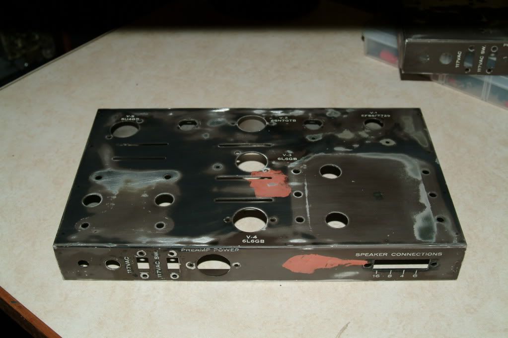
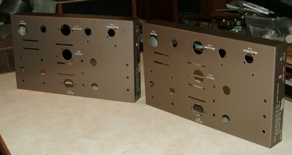
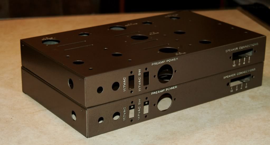
Here's the finished chasssis'. Their not perfect, but I can live with it.
Below is my approach. In hind site, there a few things I would do differently. But like any restoration, there is a "point of no going back".

DSCF0001.jpg

First I got the corner welded back together and dents gently hammered out. Resurfaced any highs and lows with Bondo spotting putty. Sanded the chassis, 400 grit then 600, getting as close to the lettering as possible.


DSCF0022.jpg

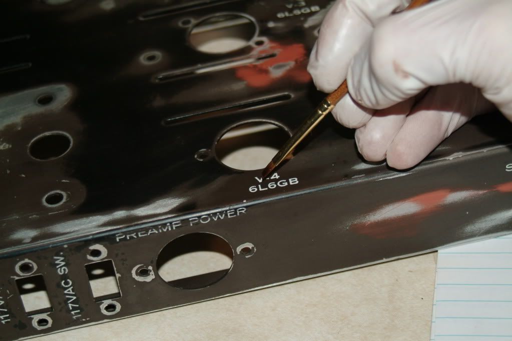
Next, I brushed a light coat of Vaseline over all the lettering. This keeps the paint from adhering in the areas coated. Had I known how much retouching I would be doing later, I would have been more accurate here...perhaps done each letter individually. :scratch2:
After the letting paint set up for 30-40 minutes I gently removed the paint over the lettered areas with a soft cloth.

colormatch9-1.jpg

Krylon's Fusion for plastic (metal also), "hammered finish"was a pretty good match (original on left / new on right). No priming and the stuff is pretty tough.


DSCF0027.jpg


DSCF0033.jpg


DSCF0041.jpg


DSCF0042.jpg

Retouching between letters and repainting some lettering.

DSCF0046.jpg


Good enough:thmbsp:

martin
 
I think that the episode above, may have just been caused by a sub-standard provider of "tubular" caps... or, a situation where ridiculously high ripple currents existed (i.e, too much load on not enough cap)... or the cap was polarized backwards...

Maybe the tubular caps of that day had poor ESR?
 
Martin -- Your work on the chassis is unbelievable! Makes me want to improve the looks of some of my Eico equipment when I see how far you were able to take yours. The Vaseline trick was way cool, and the paint you chose is nearly indistinguishable from the original. Congrats on a really great job!

Dave
 
Thanks Dave,
The really hard part was going back and painting in between the letters. The hammered metal paint dries quickly and was hard to keep it "fluid" for more than a letter or two.
Plus it needed to be constantly stirred, because hammered finish paint gets it's look by the paint separating. Lacquer thinner dried too fast and mineral spirits was incompatible.
What finally worked was Testors model paint thinner. I dries slower and helped keep the paint particles suspended.
I didn't bother retouching the bulk of the copy on the info panel. By the time I got to that area...I'd had my fill.
Like I said, It might have been easier to "mask"each letter individually.

Oh well.

Martin
 
Holy crap! Very nicely done. I can't believe how nice those came out. Congrats on the accomplishment.
Al
 
And back to the lettering and paint ...

Twere me, I'd just start from scratch. You'll never be able to get a clean finish trying to patch around the old lettering. Strip the metal bare, sand and fill as needed, and a shiny new coat to match the original. Let that set a couple days and sand to at least 600 grit for a smooth working surface. For lettering, try these guys ...

http://www.hyatts.com/art/dry-transfer-letters-1.5303

If you can get a clear scan on the original logo, they've also got printable transfer film that you'd be able to print those with a standard inkjet. You'd want to check with them as to what you could use to clearcoat to seal and protect all your hard work. Even then, I'd recommend making a test piece out of scrap metal to test it all first and see how it all works.

Don't forget to clean all the mounting points that need it for proper grounding.
 
Back
Top Bottom