EICO ST 70 - question about capacitor cans, grounds, jacks

Where are you located? Lots of us have tube testers, variac etc and would be happy to help.

It is perfectly safe to power up the Eico without the rectifier, but with all other tubes. You can make sure you have filament voltages and bias voltages.

Without any test gear - the other thing I'd suggest is to go thru the assembly manual as if you were building the unit and check each and every step. Many were never wired correctly in the first place, and it's easy to overlook a mistake you've made.

Also (and this may seem dumb) make sure you have the correct fuse in the unit. I've seen 20A auto fuses stuck in amps before!

Eventually (once it's functional) you'll want to correct the loudness circuit. I can send you the instructions via email if you need them.

Personally, if I were convinced it was wired per the manual and correctly fused I'd take a leap of faith an plug it in. If you've replaced the electrolytic caps there's nothing to reform. Most folks who built the Eico from a kit would have just done the same...

- Gary
 
The Dim bulb is working correctly. It's not indicating any large amperage draws, and what it is showing is very little. It's in series with the cord, and the current is passing thru it. High current = bright light, low current = dim light. With everything hookedup and the unit on you are getting a dim bulb.

Take the unit off and plug it in to the wall.
 
Anyway, I looked and saw a 3 A fuse in the unit.

The drift I'm getting from the forum is to plug the thing into the wall and see what happens.

However, to reiterate:

Only rectifier tube in: passed 95W dimbulb test fine
All the tubes in: lights up 75W bulb.

I'm not making up these procedures myself. I'm getting a lot of it from the Antique Radio site, which was linked from this site. Unfortunately, a lot of radios are low-wattage units, so what's useful for the radio may be too small/large for a 30 WPC amp.

I'm taking this test dead seriously because I don't want a dead amp. Nor a dead amp owner, though I'm very careful to keep my mitts the hell off the unit when it's powered up.

But if I plug 'er in and she makes music, I'll be a happy camper, believe me. OTOH, there are all those resistors that are out of spec...

But what happens with the next thing I try?

The common wisdom is: If you plug it right into the wall you're an idiot. Figure out the "intricacies" of the dimbulb circuit, make one, and test it. Go from low wattage bulb to high. If it flunks at a given wattage, you've got to fix it. But now I find out that it can "flunk" at low wattage yet pass at high.

Well, OK, it turns out that only a little current is needed to light up a 15W bulb, and the resistance of the bulb is enough that the voltage divider network set up by the amp and the bulb results in most of the voltage showing up across the bulb. Result: bulb gets nearly 15W. The current is only a trickle for a high-powered amp.

But now it's getting a little complicated, isn't it? If the amp has a finite resistance, voltage and current going into it will vary according to the wattage of the bulb in the dimbulb circuit.

It appears that the really valid thing to do is to power up with a Variac plus ammeter and look for any huge jumps in the ammeter reading.

But I was too cheap to shell out for a Variac, instead using the Poor Man's Variac, the dimbulb tester.

I think the thing to do is to use the dimbulb tester, but measure both voltage and current going into the amp. Then make a sort of chart, just like you'd do with the Variac, stepping up voltages, and looking for huge current jumps. It wouldn't be very expensive to set that kind of thing up.

But making sense of the results?? I have absolutely no a-priori idea of what's good, so-so, or dicey for a tube amp. I do know the upper limits, by the rated input power. But that's for the amp going at flat out maximum - not idling.

Now, I've searched "dimbulb testing" - really, I have - and the results are mostly on constructing one. I guess for many, many people, the dimbulb circuit is a little complicated; it is two or three things hooked together, after all... But using it? The info is a little fuzzy.

That's why there really ought to be a sticky on using dimbulb testers - practical aspects, and some very basic theory (simple application of Ohm's law, and don't worry about reactances, phase angles, complex numbers, and all that mind-frying stuff)
 
Last edited:
Get another rectifier tube if your not sure and do the diode mode with SS UF4007 (newer faster & quieter than IN4007) on the secondaries to pins 4 & 6 of the 5AR4/GZ34. It will help them last without hurting the sonics. Sure you may have some other bad tube(s), and it doesn't hurt to have spares and for testing.

http://dynacotubeaudio.forumotion.com/t1006-tube-rectifier-diode-mod


Maybe get the variac, leave the bulb in series and hook up cheap speakers. When you get to about 90 volts you should get sound. If it's humming you will want to shut it down right away.

Your line voltage may be too high anyway so the variac will help take take of that problem as well.

I assume the diode you're referring to is CR1 on the schematic (it's the only diode in the amp). I see pins 4 and 6 on the GZ34 rectifier tube connected to a transformer secondary ("red" wires from the transformer), but there's also a tap ("blue" wire) that goes thru CR1, a diode. All I see specified on the Eico parts list is 200 ma, 380 Peak Inverse Voltage rating. Shouldn't be hard to replace the thing.

The CR1 in question looks like a button and....hmmm...the d#*n thing has come un-soldered. :eek:

To be continued....
 
Right, I was only refering to the rect. tube mod where you add SS diodes in series to extend it's life. You still get the slow warmup which the 5AR4/GZ34 is great for , but it takes a good load off of it. Can't hurt to replace the CR1 as your probably doing.
 
Last edited:
I assume the diode you're referring to is CR1 on the schematic.

Actually no. It's a simple modification to the rectifier cicuit.

check it out here

Thanks for the suggestions, but once the beast is up and almost behaving itself, then the mods can be tried.

BTW, I tested the existing diode with my meter's diode testing feature, and it tested OK. So I soldered it back in place.

I know there's a list of them, the Lafferty mods, starting with the wretched Eico loudness contour. With a tube amp, though, and the speakers I have, I probably won't have a lot of use for loudness.

However, of particular interest are the mods which extend frequency response of the power amp and the phono preamp.

What's off-putting is the prospect of drilling holes in the chassis for pots. Plus, required equipment for testing after completion of the work includes a signal generator and oscilloscope. Not exactly pocket change, but then the refund from the Fed gov't will cover it. And thanks to the EchoWars DIY post, I know which oscilloscope and signal generator to get.
 
Last edited:
Thanks for the suggestions, but once the beast is up and almost behaving itself, then the mods can be tried.

I understand your hesitancy to monkey with the original desgn, but this ought to be the first thing you do once your unit is up and running.
 
I understand your hesitancy to monkey with the original desgn, but this ought to be the first thing you do once your unit is up and running.

Will do. Meanwhile I'm reading the "Sigh...Dimbulb Test Failure" thread in Solid State. It re-appeared as if by magic, with even more useful information on the fine points of dimbulb testing, including what makes an amp fail, than what I'm getting here.

All of the information from these kinds of threads ought to be collected together in a big "dimbulb-ology" topic.
 
Ok, the jig's up!

I finally plugged the consarned thing into the wall and...
the tubes lit up - beautiful lil' suckers
the amp didn't blow up - nor did it blow a fuse.

Still haven't tried it with my $6.00 Goodwill Test Speakers, but the amp is gradually clawing its way back to life.
 
Last edited:
No load? Your risking the Output Trans. You can use a 16 ohm 25W resistor for each chammel also.

Sorry, forgot to mention that I had a dummy load of 7.5 ohm 50 watt resistors connected to the relevant taps on the back. Getting weaned away from transistors slowly but surely. And, yes, I made sure to follow Eico's arcane way of connecting speakers to the amp.

I thought that 7.5 ohm would approximate the typical speaker the amp would be connected to.

Is 16 ohm preferable?
 
Actual load doesn't matter much, anything > 50 ohms should be fine. Just don't crank the volume.

Not much risk to speakers with tube gear btw.

Probably the hardest part of an EICO ST70 is figuring out the wacky input jacks and output speaker terminals on the back :)
 
Slaving over a hot tube amp...

I've been adjusting balance and bias. On channel 2, it's no problem at all; I can get balance plus or minus 5 mV. Just not coordinated enough to get it any better. Bias I can set to 380 mV, i.e., 0.38 V, to within +- 10 mV.

Channel 1's the problem, as I can't get balance any lower than 25 mV, 0.025V, even with the pot turned all the way counterclockwise. Bias I can set fine. The balance level seemed to get better (lower) as the amp warmed up, but it never really got below 20 mV.

So what's the most likely culprit?

Even with imperfect balance, I tried out my test speakers with an old DVD player hooked up to the tape inputs. I turned the ST70 on, no sound at all. I turned up the volume - no sound.

Then I realized that this ain't my Sherwood S-7100A, with the volume built into the click-on switch. Oops.

I turned up the separate level control and Michelle Shocked played as nice as you please on both channels. I could get pretty good volume. No huge channel imbalance. No scratchiness to the controls (I'd deoxited them a while back). No hum in the background, no pops or any other nastiness.

So, the tube era has dawned here. Thanks to all whose advise has helped in getting this piece up and running.

But there's a lot more to be done...how bad an effect on the sound will the out of adjustment balance be?
 
Others may have better answers, but as no one has replied here's my $0.02

I'd swap the pairs of output tubes (7591)'s between channels and see if the imbalance follows the channel or tubes. I'd bet it follows the output tubes. 25mv is probably reasonable to live with, but you might swap around individual tubes to see if you can make "better pairs".

As always, thanks for the advice!

I've started it up again today and played it for a while, this time hooked up to my decent speakers. The taper on the level control must be a little different than what I've been used to, because I only have to turn it up a little, about 1/8 of the way, and I get really substantial volume. This amp can pack a wallop.

The music just seemed bigger with this amp, though I think that I may have inadvertently played it at higher volume than otherwise. Always have to beware of the "louder always sounds better" effect. OTOH, it was a loud sound that I didn't want to run away from.

Anyway, eventually I came to the sad realization that maybe I should check balance and bias. This time, both channels were able to balance to as near zero as my fingers and stiff little pots could get; about +- 5 mV or so.

I'd thought the inability to zero the balance would have something to do with out-of-spec resistors, which seem to make up about half this amp's complement of resistors. Replacing resistors I guess will be the next big phase of the ST 70 project. Advice on any resistors that should be considered first would be welcome.

I'd been playing the amp with a CD player through the tape inputs. When I tried my turntable, it was a disaster! Lots of hum. OTOH, the TT I tried was my Sony PS-LX2, which does not have a ground wire. I may try the Pioneer PL-112D, which does. If that doesn't help, some more work on the project to do!
 
Actual load doesn't matter much, anything > 50 ohms should be fine. Just don't crank the volume.

Not much risk to speakers with tube gear btw.

Probably the hardest part of an EICO ST70 is figuring out the wacky input jacks and output speaker terminals on the back :)

Hey Gary, ever crank a tube amp way up with dummies and listen to the music from the OPTs? That freaked me way out the first time it happened. :D
 
Hey Gary, ever crank a tube amp way up with dummies and listen to the music from the OPTs? That freaked me way out the first time it happened. :D

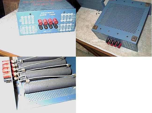
I haven't - I picked up one of the Heathkit speaker ID-5252 loads a few months ago.
id5252.jpg
It handles a good bit of power, I'll have to give it a try.

- Gary
 
Back
Top Bottom