Well I've been running this amp for a while now and thought I'd post an update. I got the amplifier unit itself running well after replacing most of the caps and resistors, but the more I worked on it, the more the age of the components concerned me. There was a particular problem with the connector between the power supply and amp. I temporarily bypassed this by connecting heater, ground and B+ connections with separate wires.
Then, recently, I located a supplier of the obsolete Belling Lee parts and I knew I could restore the connectors. When the parts arrived I decided to go for a complete teardown, respray and rebuild. The respray gave me some problems as the metal primer didn't bond well with the steel transformer covers, but I went ahead anyway. The result is shown in the pictures. Despite careful handling, two tiny flakes have come off the transformer covers, so they'll need attention sometime.
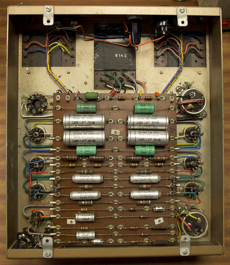
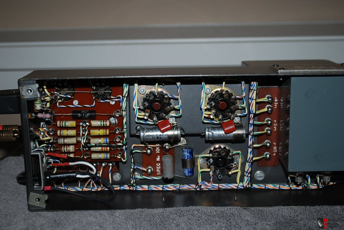
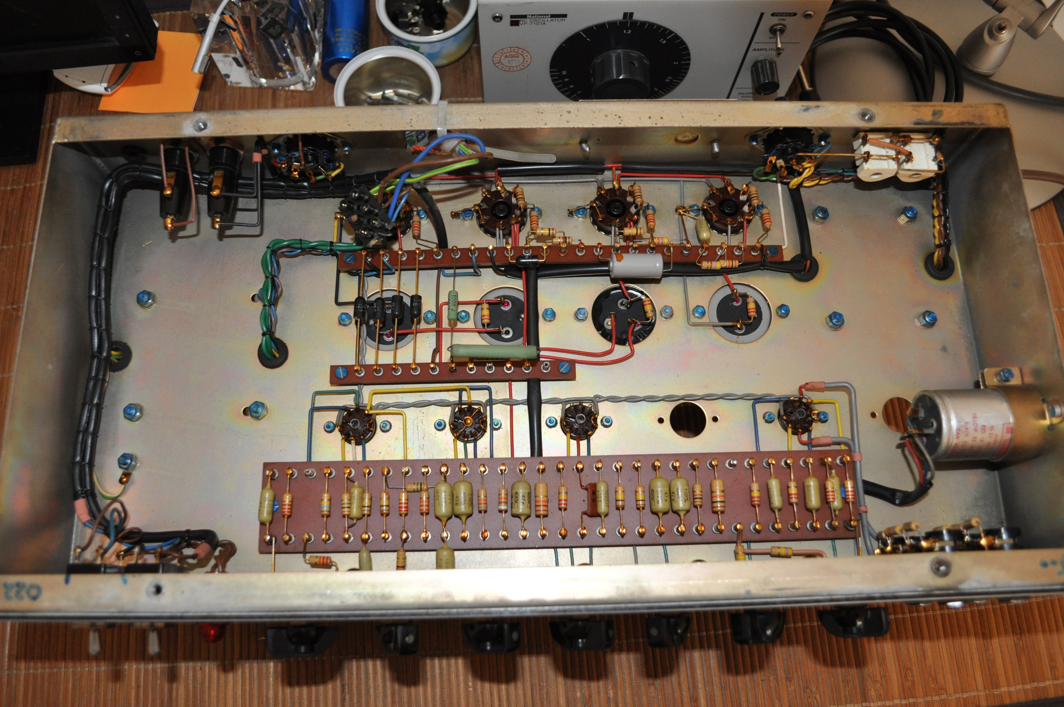
Despite problems with the paint job, I was glad I stripped and cleaned it completely as there was some age-related corrosion everywhere, including under the transformer covers. (See pic.) At one point the power supply and amp must have been stored in damp conditions. As I only have external Belling Lee connectors for one cable, I took two of the four power connections out of commission, and that allowed me to reduce the thickness of the wires for the power to the filament heaters.
It was very satisfying getting it all cleaned and rebuilt with new wiring. I couldn't restore the neon power indicator and one of the fuse holders broke, revealing and earlier glued repair, so there are a few new components. The ground buss turned out to be copper, just very corroded from the decades.
My wiring is also not as neat as the excellent original, but I still intend to stick the cables in place using silicone, as I've seen Dave G do with caps. I was amazed at the care taken with the original build, except that the builder located the two mains inlet fuses right over the rectifier! Not wanting to mess with the chassis, I have left them there.
With the power supply restored, I'll get on with the amp itself. Aiming for a better paint job.
I'm looking forward to learning more from studying the work of the late builder. I added a detail of the Belling Lee connector and braided cable as these vintage connectors may be as unfamiliar to others as they were to me.
View attachment 1046550 View attachment 1046552 View attachment 1046553 View attachment 1046557