

My son is bringing his Red Bear MK 120 over next weekend to have the sockets retentioned. It's supposed to be based on the Hiwatt with a little Marshall thrown in. It sports a quad of Russian 6n3'sI don't agree with this at all.In fact,many manufacturers (especially in England) produced consumer-grade equipment that could easily meet MIL Spec.And any of these units could have been found in the average home. Well,maybe not the Hiwatt
Compare these photos with the OP's and you can't miss the influence.
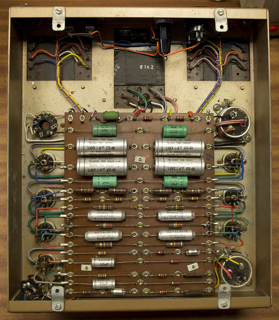
Leak:
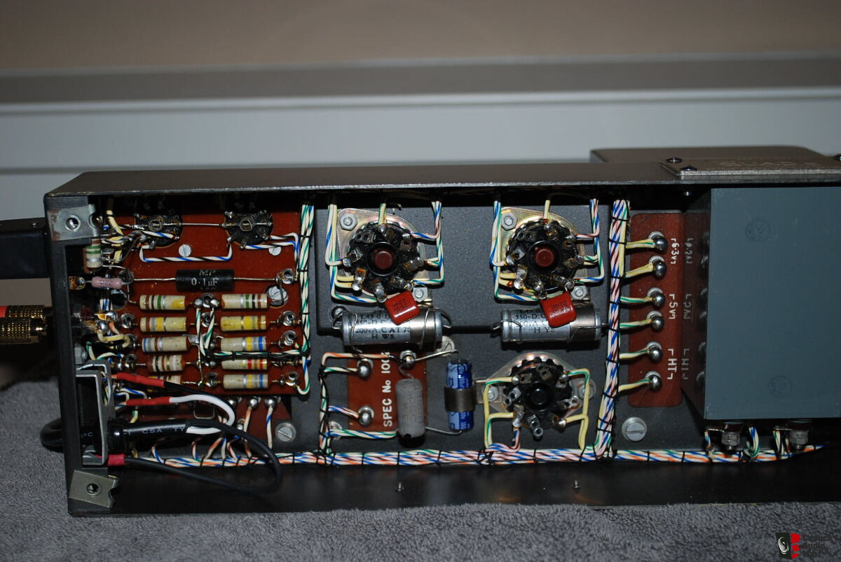
Quad:
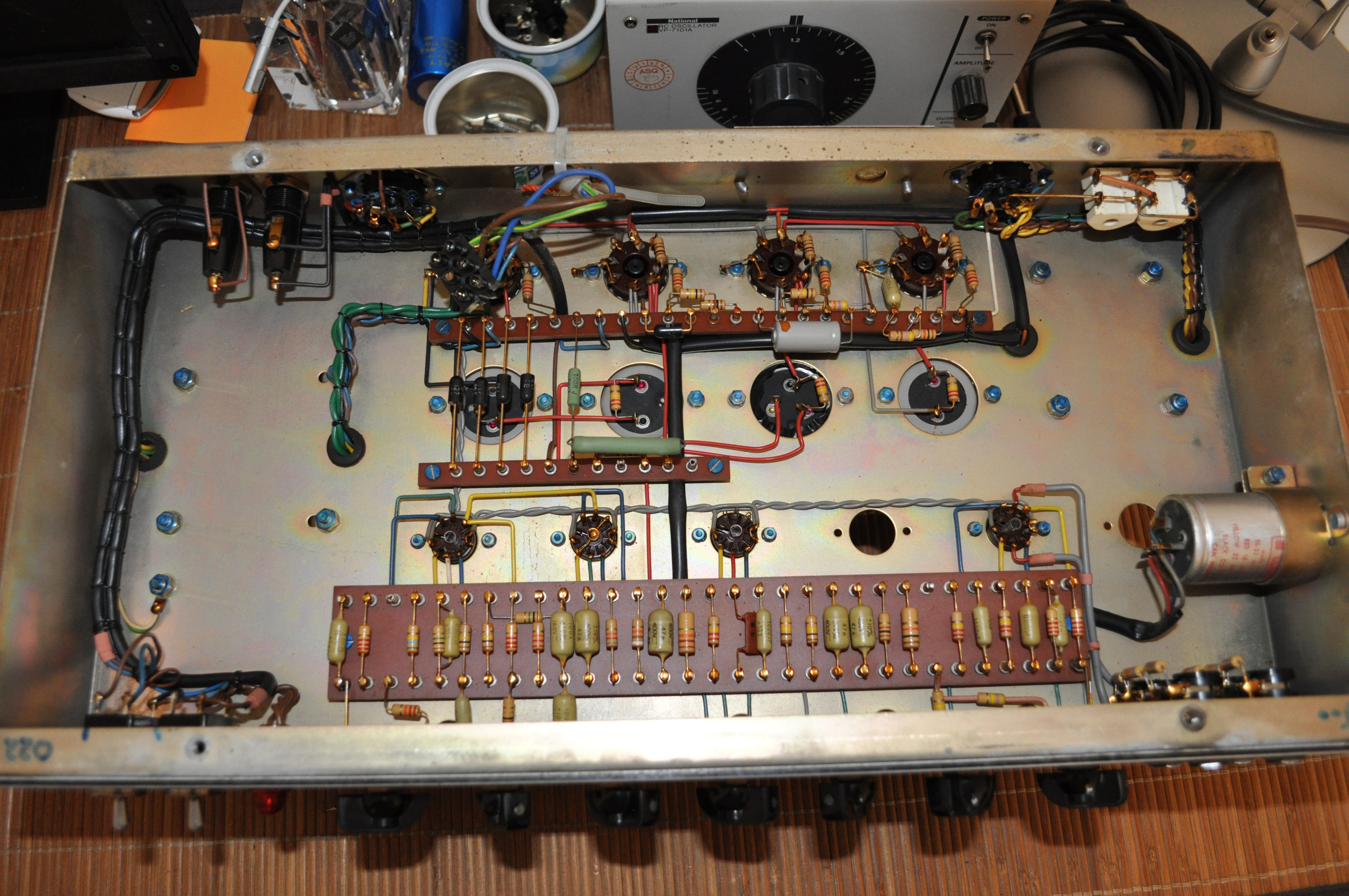
Pye:

And even musical instrument manufacturers;
Hiwatt:

Damn that thing gets loud with his four driver cab!


