first tubes pioneer sm 801

Hope everyone had a nice thanksgiving.

Larry, I got the voltages you asked for, still waiting for the cap to make my signal tracer.

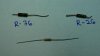
R95 is a big resistor on top of the chassis it has -28v after the resistor before c54. Since this is a negative voltage am I correct to assume it is a bias circuit for V1V2 ?

I have 440v @ c51

I have 496v @ the junction of D4/c52/r93.

Something odd to add. With my N.O.S. 6an8 tubes the sound is much worse, much weaker and my right channel becomes way lower than the left.

When I put back the O.E. tubes both channels are pretty close, sound is pretty good its just weak, won't get very loud.

The tubes they sent were two different brands, RCA and GE, so if matching is important these are likely not. Should I order another pair from a different vendor?

I played with the scope for a while but could not get a sensible trace from the little hook on the front that says "cal .3v" which I assume is a point for calibrating. Anyway probably best to stick with the Pioneer and not get sidetracked trying to figure out this scope.
 
So I was going through and checking resistors today and came across the following; On the schematic R-26 and R-76 should be 1k ohm. The color code on the resistors was N-K-G-S which I think is 1k ohm +- 10%. Out of the circuit they measured 1.4M ohms and 1.9M ohms which, if I'm converting my M's to K's correctly, they are out of spec.

I replaced them with some 1k resistors that I happen to have (see photo). These replacements are smaller, I do not know how to tell what wattage a resistor is rated for. When I applied power (through a Variac) smoke came out from somewhere. I yanked the plug before I could tell exactly were it came from. The replacement resistors do not appear to be damaged and they still measure 1k ohms.
 

Attachments

  • P1050841.jpg
    P1050841.jpg
    25.5 KB · Views: 8
  • P1050842.jpg
    P1050842.jpg
    78.9 KB · Views: 11
  • P1050843.jpg
    P1050843.jpg
    99 KB · Views: 9
O.K. so the green band is a multiplier of 100k ohms not 100 ohms. So, while still outside the tolerance, the 1.9 M ohms is only a factor of 2 off? Anyway do you think the schematic is wrong? It for sure says 1k @ R-26 and R-76 but I have read that Japanese schematics of the era are notorious for mistakes.

Can anyone make an educated guess about what would leak smoke if pin 7 of the 6an8 tube had 1,000 ohms less resistance to ground than it is supposed to?
 
The schematic is wrong. I put in 1Mohm resistors and no smoke. Right channel is now a little weaker than the left so I might have damaged something. Switching the 6an8s did not switch the lower channel.

I think I'll walk away for a while.
 
It's possible that the schematic is wrong. As it's working with the 1mohm and the 1kohm reversed, go with it.

I wouldn't worry too much about the GE vs. RCA. I mix them all the time. It's possible that the problem is further back in the chain. I'd hold off until you get the cap then start at the inputs and compare each point(both sides) until you get a difference. I don't think it's in the 6an8's.

Have you ohmed out the balance pots to center them up with the knob off. Once that is done then put the knob back on. It's possible that it's off center.

Actually a Green band signifies megohm. Get this resistance calulator.
http://myfreewares.weebly.com/resistor-colour-code-solver.html
It's very good. You can either enter the colors or the values and get what's needed.

Old Acronym..Politically incorrect but this is the way I learned it back in the 60's.
Bad boys ravage(nice term for it) our young girls but Violet gives willingly

Bad- Brown ............0
Boys - Black ...........1
Ravage (nice term) - RED ...............2
Our - Orange .........3
Young - Yellow ......4
Girls - Green .........5
But - Blue .............6
Violet - Violet..........7
Gives - Grey ............8
Willingly - White.......9
 
First let me share what can only be described as audiokarma, yesterday when going to the grocery store I stopped by the Goodwill outlet as I often do, and what do I find tossed in the bins with the usual crap, an old Heathkit signal tracer model IT-12. It even seems to work.

After the fiasco with the resistors, and swapping the new 6an8's back in as well as cleaning the pins here is were things stand.

The output of both channels is equal! This happened after I replaced the resistors or installing the driver tubes. I did both at the same time so I don't know which did it.

The output remains weak @ 1/2 volume its about speaking level. At 3/4 volume its not much louder and it starts to sound distorted.

Using the signal tracer on the 6an8's pin 3 has a strong clear signal, pin 1 is weaker and not as clean. It is the same case for the other 6an8.

Pin 8, were the signal comes in, is pretty clean although not very strong. If I turn up the volume on the signal tracer it becomes audible. Applying the signal tracer to the coupling caps at this volume setting it is quite loud out of the speaker of the signal tracer. Much louder than the speakers hooked up to the Pioneer.

My wall voltage is ~ 122v. With wall voltage my plate voltage is 505, 511, 510, and 511.

I tried tracing the signal back into the preamp, from pin 8 it goes to the volume pots, they are two pots, one in front of the other, and the output was kind of confusing and I ran out of time.

I don't really know what question to ask at this point. It seems like were getting close. It just seems like there's not as many electrons moving as their should be.
 
Hey Greg, top marks for enthusiasm! This Pioneer repair may seem endless, but you are learning as you go along, and this will help you with your next amp repair... there will be others. :) Have a good thanksgiving break.

Thanks for the encouragement, although at this point I think its more obsession than enthusiasm. But, whatever gets the job done!
 
You keep falling in shitpiles and come up smelling of roses! LOL!!! I'm JEALOUS!!


Signal flow on the 6an8 should be pin 8 --> pin 6,7&9 -> Pin 2 -> pin1 & 3, then off to the output. Look for gain between pin 8 and 6, 8&7, 8&9 and again from pin 2 to pin 1. You'll need a DVM for this. I still think the problem is before the 6an8.

With a source hooked up to AUX (siggen or a tone generator set to 1kHz) get a tone going. Check input and output voltages of both sections of the 12ax7's. Then the output of the 12ax7 vs. the input of the 6an8 @ pin 8.

One more thing, short together the CENTER TAPS of the Volume pot. This will tell us if the pot's are off or not. (imbalance). If the sound changes and becomes equal, the pot's aren't equal. So 1 of 2 choices, live with it and use balance control, or replace the volume pot.
 
First some more basics to clarify. The pre-amp has four 12ax7 tubes, when I run the test tone thru the AUX circuit I do not pick it up at two of the tubes because they are only for the Phono section and will not be in the loop when using AUX.

If the above is true, are these two tubes for the phono section the one labeled V1 and V2?

If so, good I can forget about those for now.

I will report the voltages for the input and output of the 12ax7's as soon as I'm certain that I am measuring correctly, but I found something curios to report. The 12ax7 for the left channel( V3?) gets its heater voltage from pin 7 of one of the 7591 tubes (I think its V9). The 12ax7( V4? ) for the right channel gets its heater voltage from pin 4 of the 6an8 of the right channel (V6).

The heater voltage on V3 is 6.1 V ac. The heater voltage on V4 is 2.7 V ac.

This does not seem right.
 
Another anomaly, pin 7 of the 6an8 tube in the right channel reads -.320V dc. Pin 7 in the left channel is 6.4V dc.

If I am reading the schematic correctly these are on of the grids?

I assume these should be the same?
 
More food for thought.

I went back and probed pin 7 to make sure I was getting good contact, in doing so my probe hit the ground side of r-26 and the test tone got LOUD.

This is the resistor that is marked as 1k on the schematic. The one that was installed was for sure-Brown, Black, Green, Silver. It looked like all the others in the unit so I am guessing it is from the factory. I replaced it with a resistor with identical color code (1m ohm?) after trying the 1k ohm that made smoke leak.

There is also a 3u 150v electrolytic capacitor on this pin that I think I may have installed backward at some point ,I will get a new one.
 
O.K. sorry, now I think I see what I did.
R26 is 1k, R27 is 1M so I must have C21 in backward.

So I flipped C21 and C45 and now the left channel is pretty strong, maybe even fully functional. Right channel remains very week.

Voltage on pin 7 of the left channel is now 40v dc.

Voltage on pin 7 of the right channel remains ~ -.33v dc.

Will order new caps C-21,C-45.
 
Almost there.

I put in new caps at pin7 of the 6an8's. The left channel sounds GREAT!

The right channel remains weak.

The voltage on pin 7 of the good channel is~ 56v. Pin 7 on the weak channel is -.3v.

Other discrepancies; pin6 is 109v on good, 208 on bad.

Heaters, pin4, is 6.3vac on good 2.8vac on bad.

Pin 9 is 1.4v on good .03 on bad.

Pin 4 on the bad channel comes directly from the hum balance pot on the back. The good channel 6an8 gets its feed from pin 7 of V8.

If I peg the hum balance pot I can get pin 4 up to 3.5vac, channel remains weak.

I am very tempted to grab heater voltage from a 6.3vac source but I won't until I here from you, Larry.

Also pin 5 has 2.5vac maybe that's were the rest of the heater v is coming from?

I did try swapping tubes, no change.
 
Funny reading this thread at the beginning and now at the end. You went from "whats a variac?" To sounding like an engineer. Awesome. And good luck.
 
Kinda like jumpin in the ocean to learn how to swim.

So I have 400v out of c51 it sp

lits off and goes through R81 and R31, both of which are in spec, and then on to pin1, the plate. On the good channel I have 273 volts on the plate on the bad channel has 215v.

I have checked all the resistors and they are close enough. About the only thing I haven't checked or replaced is a mica capacitor on the grid of the pentode section (I think).

Also I reported erroneous reading on the heaters, they are now all even @~2.9vac. I was checking them before with the 12ax7's from the phono section removed. So pin 4 and 5 @~ 2.9vac on each is that O.K. ?


On the pin 3, the cathode?, I have 199v on the good channel and 103v on the bad .
 
When you are checking the heaters are you checking with both probes on the tube pins or one probe on the chassis? AC Voltages for tube heaters get measured across the tube pins, not referenced to ground.


One of 3 things come to mind. with your readings at times.
1-Flaky batteries on your meter (they don't last forever),
2-flaky probes for the meter (they can go bad with constant bending and flexing), and 3-bad tube socket or cold solder joints.

If you are getting 2.9vac referenced to ground that should be right about 6.0vac with the probes across pins 4&5 on the 12ax7's.

The problems with the 6an8 on the right side almost sounds like it's a bunch of bad connections, lousy wiring, or a bad socket(meaning poor contact and erroneous measurements). Take a dental pick and tighten up the leaves where the tube pins go in. and give them a spritz of DeOxit and then pump the tube in and out a few dozen times.

Larry
 
So in going over things one more time I find that at some point I put R77 on the wrong lug, put it where its should go, and just like that it works!

Larry, I can't thank you enough for sticking with me through all my mistakes and questions, your patience and knowledge is an inspiration.

And to everyone else who helped along the way thank you as well. It sounds as good as everyone thought it would.

I do still have slightly different voltage on the cathodes of the cathodes of the 6an8's, but I think I will enjoy it for a while before any fine tuning.

Thanks again,

Greg
 
Back
Top Bottom