A few months ago I treated myself and bought a 100-T Coronet tuner/preamp.
It was advertised as working on AM but not on FM. When I received it, I discovered that the seller was telling the truth. AM worked great. FM was dead.
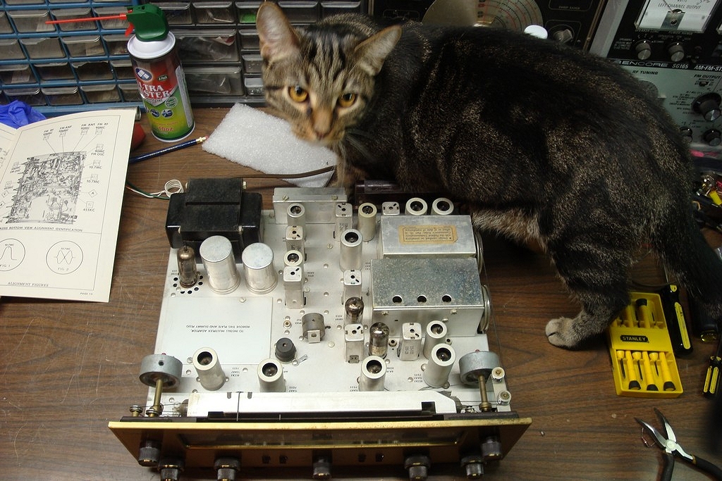
After I put it on the workbench, Viktor the cat had to inspect it to make sure it was to his liking. He approved, so I proceeded.
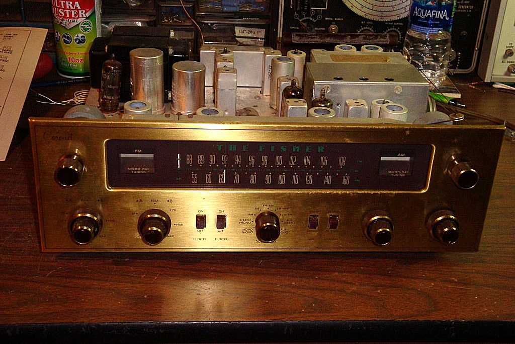
Without flash
I have replaced the few dog turd caps it had, rebuilt all of the electrolytic cans, and replaced the original selenium rectifier with 1N4007 diodes and a terminal strip. I found that a 39 ohm resistor across the two 500 uF caps, in place of the original 30 ohm resistor, was enough to keep 12AX7 filament voltages very close to their original levels.
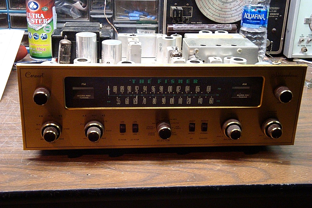
With flash
I do not have the original Fisher service manual but I have the Sams Photofact for this set, so that is what I used to go by in servicing it.
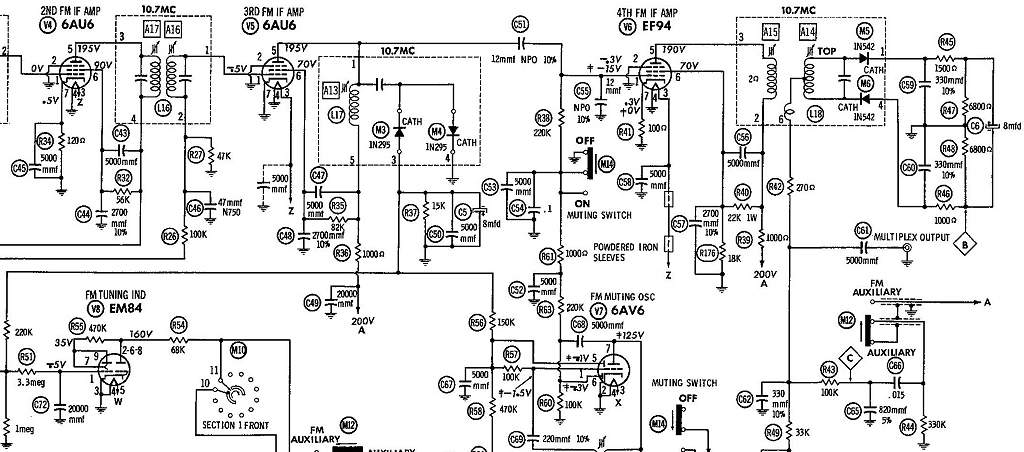
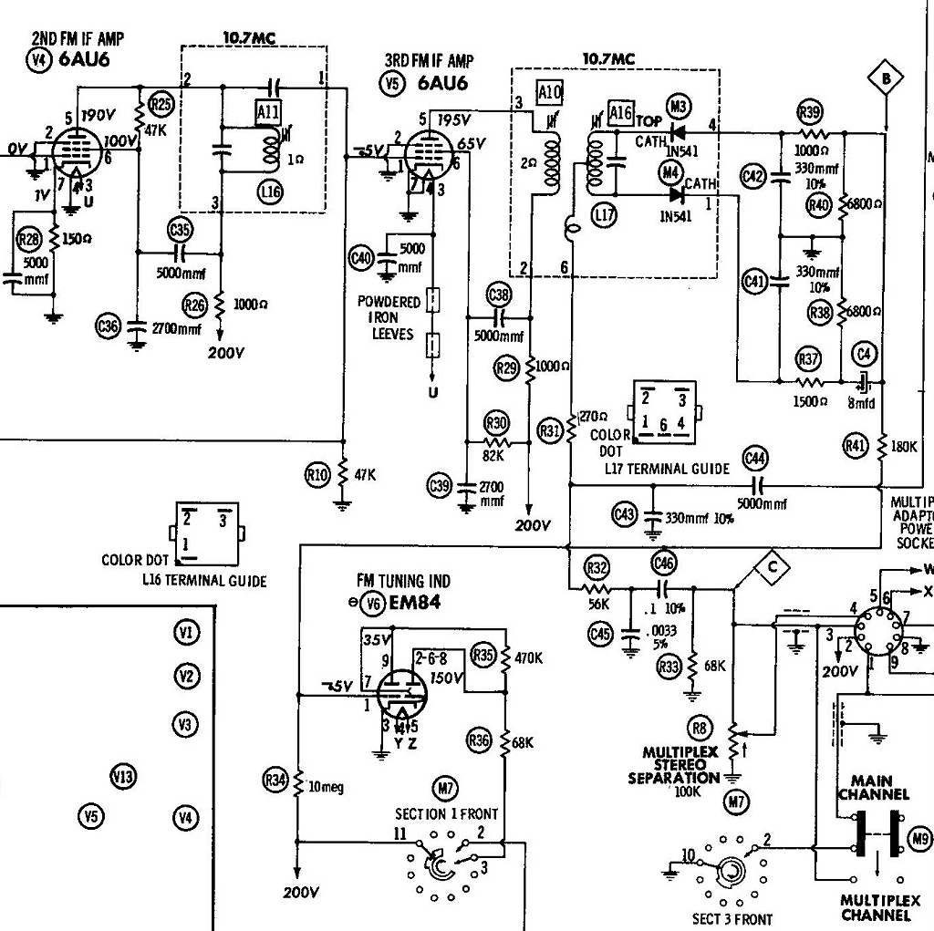
I discovered there was no plate voltage at the 2nd FM IF amp tube. The 3rd FM IF coil (single coil transformer) showed infinite resistance.
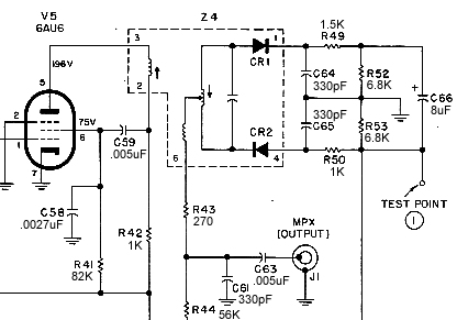
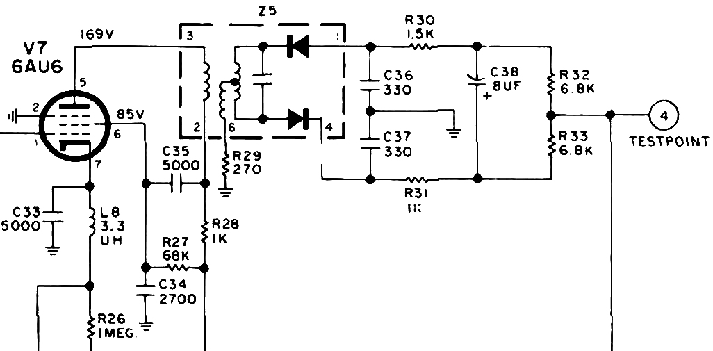
I pulled a similar IF coil from an FM-50-B chassis. While I was at it, I replaced the ratio detector transformer with one from an FM-100-C chassis to get the "wide band" transformer as my intention was to eventually add a WX multiplex decoder.
Once I did all that, FM was back, but was very weak. Alignment using a VTVM was not much help. I could not get my scope to display the waveforms which the Sams manual was showing, so I used the VTVM instead.
I could not get anything out of the null adjustment on the ratio detector transformer. It was as if adjusting the slug had no effect.
Upon inspecting the original 3rd IF coil, it looked clean - no indications of silver mica disease. So I opened it up and found that one of the wire leads was broken right at the solder terminal.
I removed one turn of wire, resoldered the lead to the proper terminal, and then I removed the FM-50-B 3rd IF and reinstalled the original.
After I did that, FM performance improved noticeably.
However, four problems remain:
1. While FM is now loud enough that I can hear the inter-station noise, it still seems to be lower than it should be.
2. I still cannot adjust the "null" of the ratio detector.
3. The FM magic ray indicator - instead of the shadow narrowing, it widens when I tune in a station.
4. It seems to be "double-spotting" when tuning. In other words, when tuning in a strong station, it is as if it has two peaks, one better than the other. I realize this is likely an alignment issue, but until I can get FM to be a bit stronger/louder, I don't think a realignment is going to help at this point.
Yes, I did replace the 8 uF electrolytic in the ratio detector circuit. I had read in another Fisher thread that this electrolytic should be installed backwards when replacing the ratio detector transformer with a "wide band" unit since the internal diodes are reversed, so that is what I did.
Any help on this would be very much appreciated.
Happy New Year to all!
It was advertised as working on AM but not on FM. When I received it, I discovered that the seller was telling the truth. AM worked great. FM was dead.
After I put it on the workbench, Viktor the cat had to inspect it to make sure it was to his liking. He approved, so I proceeded.
Without flash
I have replaced the few dog turd caps it had, rebuilt all of the electrolytic cans, and replaced the original selenium rectifier with 1N4007 diodes and a terminal strip. I found that a 39 ohm resistor across the two 500 uF caps, in place of the original 30 ohm resistor, was enough to keep 12AX7 filament voltages very close to their original levels.
With flash
I do not have the original Fisher service manual but I have the Sams Photofact for this set, so that is what I used to go by in servicing it.
I discovered there was no plate voltage at the 2nd FM IF amp tube. The 3rd FM IF coil (single coil transformer) showed infinite resistance.
I pulled a similar IF coil from an FM-50-B chassis. While I was at it, I replaced the ratio detector transformer with one from an FM-100-C chassis to get the "wide band" transformer as my intention was to eventually add a WX multiplex decoder.
Once I did all that, FM was back, but was very weak. Alignment using a VTVM was not much help. I could not get my scope to display the waveforms which the Sams manual was showing, so I used the VTVM instead.
I could not get anything out of the null adjustment on the ratio detector transformer. It was as if adjusting the slug had no effect.
Upon inspecting the original 3rd IF coil, it looked clean - no indications of silver mica disease. So I opened it up and found that one of the wire leads was broken right at the solder terminal.
I removed one turn of wire, resoldered the lead to the proper terminal, and then I removed the FM-50-B 3rd IF and reinstalled the original.
After I did that, FM performance improved noticeably.
However, four problems remain:
1. While FM is now loud enough that I can hear the inter-station noise, it still seems to be lower than it should be.
2. I still cannot adjust the "null" of the ratio detector.
3. The FM magic ray indicator - instead of the shadow narrowing, it widens when I tune in a station.
4. It seems to be "double-spotting" when tuning. In other words, when tuning in a strong station, it is as if it has two peaks, one better than the other. I realize this is likely an alignment issue, but until I can get FM to be a bit stronger/louder, I don't think a realignment is going to help at this point.
Yes, I did replace the 8 uF electrolytic in the ratio detector circuit. I had read in another Fisher thread that this electrolytic should be installed backwards when replacing the ratio detector transformer with a "wide band" unit since the internal diodes are reversed, so that is what I did.
Any help on this would be very much appreciated.
Happy New Year to all!