Fisher SA-300B Set-up and Bias Adj. Question

Dave,
Thanks for the explanation. It helps a bit but I'm apparently a little dense.
First:
There is very little that can go wrong with the AC balance function. Check that the 30 vac is being applied to the wipers of the AC Bal controls via the coupling cap, the value of the 3300 ohm resistors supplying the B+ to the wipers, and that the switch, and coupling cap are all operational. There's really little that can go wrong with the circuit.

OK-So these components were all replaced during the rebuild with matched 5% mil spec Allen Bradley carbon comps and a tested high temp 96p series vit q capacitor. What threw me off was that when I used the Fisher method, there was no difference in what I measured at the speaker terminals regardless of where the ACB control was set, either full CCW or full CW. Perhaps my meter was not sensitive enough for the test as described. (Aw shit, I just realized I may have left the meter set to read DC which would explain my results taken at the OPT secondary's. I'm leaving this in the post for the benefit of others who may make the same mistake).

Looking at the schematic it seemed like a logical place to focus my attention might be to have the plates of each section of the AF/PI 12au7 tube provide equal voltage to the output stage top and bottom. At least the position of the ACB control was affecting the measurements taken at these two points. I suppose this approach naively assumes that everything after the AF/PI stage must function dynamically balanced and why using a distortion analyzer keeps popping up in articles I read about ideally setting the ACB properly. Since I did actually match and replace each of the resistors and caps to the output stage, perhaps balancing the 12au7 plate voltages at least provided me with a good starting point, the final adjustment remains to be seen when I use an AC meter at the output this time around. (What a dumb ass I am that it took me two days to realize).

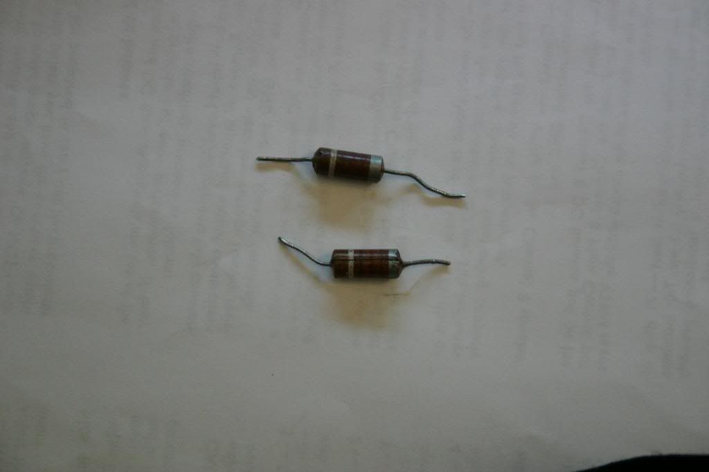
The other issue-the 220pf capacitor coupling the 410v supply directly to the plate of the ECC82 AF amp stage (and not directly to the plate of the complementary PI). If I understand you correctly, this is a local feedback for the output stage rather than global feedback for the channel. How would value drift affect the amp? It's impossible to source a 220pf bumblebee or paper cap, all that's available is either silver mica or ceramic. Every other pf range capacitor in the amp is ceramic, were the bumblebee's more stable than ceramic and should I replace the bumblebees with silver micas if I suspect the bumblebees have become damaged or otherwise out of tolerance?

More succinctly, why do you thing Fisher put a bumblebee cap right there and only there? And if damaged or suspected damaged, WWDD? Do you think a silver mica would add clarity to the sound compared to a bumblebee?

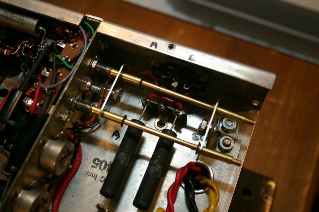
Lastly, about the observations made regarding the orientation of the mains transformer on the X-1000. I thought the optimal orientation for any mains transformer was to place it so the strongest magnetic lines of force emitted were aimed 90 degrees away from the OPTs to minimize flux interference. The placement of the mains transformer on the SA300 puts the lamination plates at 90 degrees to their respective OPTs in the same vertical plane directing the lines of force in different directions whereas placing a mains transformer on it's side still allows the lines of force to cut across the lines of force of the OPTs, albeit in another plane. Wouldn't the orientation used on the SA300 be the most ideal?

Your thoughts?

Rich
 
As long as the magnetic fields and lines of flux don't couple, you're all set.
The only difference in orientation between the X-1000 and the SA-300 is that the output transformers are bell housing up on the X-1000.
 
Rich -- The 220 pf cap is not a local feedback cap but rather, a component that tailor's the HF response of the amplification stages such that that response, coupled with the response of the OPT, then allows the NFB that is applied to remain stable.

As a basic point of understanding, NFB seeks to improve the frequency response of the circuit it is applied to to an infinite value. Of course, it can never accomplish this, but that's what it tries to do anyway. The problem is the output transformer. It's coupling is less than perfect at supersonic frequencies, and includes resonate frequencies due to complex circuit of capacitance, resistance, and inductance it represents. As a result, it can actually reverse the phase of supersonic frequencies, such that the same feedback that is negative throughout the audio spectrum, becomes positive in the supersonic spectrum. If that is allowed to happen unchecked, the amplifier becomes an oscillator.

The answer to this is to tailor the HF response of the active amplification element, so that its response is less than that of the OPT transformer. That way, the response of the completed amplifier when NFB applied is not so great as to allow the gain of the FB system to exceed unity at the frequencies where the OPT can stir up problems. This is also the reason that an OPT of exceptional quality is needed for high fidelity applications: It needs to have any resonate frequencies occur so high, that by the time the response of the circuit is rolled off to get beneath these resonance frequencies, the roll off does not extend down into the upper portions of the audio region. To prevent that from happening, a quality power amplifier typically must have a stabilized HF response (within 1 db) to at least 40 kHz. That way, the roll off produced by the components in question (the 220 pF cap) will be well above the audio frequencies, leaving the audio bandwidth to 20 kHz very flat.

The cap in question could have just as easily been connected to ground instead of the B+ source to accomplish its primary function, as that source represents an AC ground level anyway due to the presence of the power supply cap connected there. As to why they chose the 410 volt source, or used the type of component they did would likely be answered by the caliber of components they had available at the time the unit was produced, the layout of the build, or just which connection appeared to work best in the final build.

I hope this helps!

Dave
 
Dave
After I read it over a few times, yes...it makes more sense. I've looked at a lot of schematics over the past few years and never saw that connection before. I've seen it to ground, never to the B+. Thank you again.
Rich
 
The Dynaco MK III does the same thing with that cap. I suppose you could experiment to see what changes between connecting it to ground, or the B+ connection point, but whatever change there might be would be so small as to be inconsequential.

Dave
 
IMG_4240_zps7844461e.jpg

These are the two 220pf bumblebee caps I've been wondering about. You can't see it from the photo but they have slightly split and bubbled visible from the underside. I don't have a meter able to check their value so last night I replaced them with silver mica's. It's been a few days since I started up this amp after the rebuild, so I also set the AC balance (with a meter set to read AC this time) re-biased the tubes and set the DC Balance on the amp. What an improvement to the sound. Fully tight, clear and powerful. What impresses me the most is how clear this amp plays during complex musical passages no matter what the volume, never showing any signs of a struggle. None of my amps have ever shown such control during playback, no matter what the volume. Makes me wonder what I might have done wrong with them and what can I do about it?
Band of Gypsys was amazing this time around (and I haven't even played the vinyl copy yet). Red Hot Chili Peppers are not a group I listen to very often, but the attack, power and image from this amp playing "Blood Sugar Sex Magik" really impressed me last night and this morning. A very clear sounding singular image and soundstage, not a left/right speaker kind of sound.
I've been showing restraint but already twice this morning my wife has come in to the den and glared in silence at me. Anybody else ever get that??? I would tell her I saw a $500 bill stuck in a tree down the street if I thought it might get her out of the house long enough for me to crank the volume. I'm dying to really hear this thing breathe.

IMG_4238_zpsbd21e866.jpg


I don't always drink beer when I listen to music my friends. But when I do, Jimi Hendrix may have been the most interesting man in the world.
 
All Along the Watchtower -- and can you believe it?.......Summer Rain as performed by Johnny Rivers!

Nothing replaces ample power for your needs........

Dave
 
heyraz;7840647I've been showing restraint but already twice this morning my wife has come in to the den and glared in silence at me. Anybody else ever get that??? I would tell her I saw a $500 bill stuck in a tree down the street if I thought it might get her out of the house long enough for me to crank the volume. I'm dying to really hear this thing breathe. .[/QUOTE said:
It's called "Lack of WAF". I get the "HAIRY EYEBALL" everytime I turn on the Stereo. Unless I'm on headphones she's screaming TURN THAT THING DOWN from across the house, and I haven't turned it up past ONE on the Volume. BUMMER!!!!!
 
My normally neat and organized work area becomes very cluttered during each project as I work. I can't seem to control the mess. Parts bins, tube tester, meters, tools, everything seems to end up in the clutter. I have days of cleaning to do. At one point last night I had 5 dmm's connected simultaneously to the amp as I measured and adjusted according to the instructions. I built sets of pomona stackable test leads weeks ago to accomplish this and other tasks.
What a mess. I have less than a week to get the room back in order before my wife gets her Irish up (the other half is Cuban). If you guys don't hear from me next week, I might be in a shallow ditch buried with my tools. I'm pretty sure my wife believes it is possible to die and take it all with you.
"Happy Wife=Happy Life" is a survival euphemism.
 
heyraz,
Did you do a before/after for replacing those bumble-bee caps? Did it affect the HF output?
Where did you source the caps?
 
Did you do a before/after for replacing those bumble-bee caps? Did it affect the HF output?
Where did you source the caps?

Yes. With the bumblebee caps (before) the sound was not as crisp and clear. After they were replaced with Silver Mica's (CD) from Mouser-very clear every way around. Night and Day. I can't think of another explanation. I have film caps on order, when they arrive I'll see if they change anything.
 
Finally....it's done.
The amp has broken in very nicely. I can't even think of a reason to replace the silver mica cap mentioned before with film caps because I like the way the amp sounds as is.
And by the way, it took more than a month till it really started to sound sweet.
The only thing left on my list was to extend the shafts from the two individual bias controls so they could be easily accessed in the same manner as the DC and AC Balance Controls without having to remove the bottom cover.

Pictures tell the story.

First the parts. All from Lowes-1/8" brass rods, "E" clips, flat drilled straps, steel caps and some brass inserts from the plumbing department. Tools used: Scroll saw to cut and notch the brass rods for the screwdriver slots and "E" Clip notches. I used a flat file to taper one end of each rod into a screwdriver tip to fit in the new individual bias pot slots. I also used the scroll saw to cut the flat plates to size.
A drill press was used to accurately drill all holes and "Suzi Loves Cowboys" Nail Lacquer was used to paint the steel caps to match the chassis. You won't need much of the nail lacquer, so there will be plenty left over if you decide to do your nails to match your amp (toes included).

IMG_4245_zpsd597246e.jpg


As I mentioned, the brass rods were filed to a taper on one end and a slot was cut into the other end to accept a screwdriver. These became the extension shafts. The trick was to fit the taper end into the slot of the potentiometer and keep it there. I drilled the flat straps to hold the brass inserts (which support the shaft) and held the rods in place with "E" clips after cutting notches into the rods (extension shaft) at the appropriate places to ensure a snug yet free moving fit. You can see from the photos how the two flat straps are supported at either end:

IMG_4247_zps4685375a.jpg


Now the extension shafts sit just inside of the amp behind the end cap. Two 3/8" holes were drilled through the end cap to allow access from outside of the amp, exactly like the access holes for the AC/DC Balance controls. These two new holes will be covered with the steel caps painted to match the chassis.

IMG_4246_zps240f7a93.jpg


The finished and assembled project without the steel caps:

IMG_4248_zps53c215f2.jpg


Bias test sockets installed and connected to meters, the amp was easily adjusted fully assembled. The meters on the lower left are reading the voltage at pin 8 from each pair of output tubes as specified in the Fisher instructions. The four meters on top are reading the voltage drop across 1 ohm resistors in the cathode circuit of each test socket. Who's got more meters than me? (And there's still one more meter out pf view reading the mains voltage coming from a variac set to 117VAC for this procedure).

IMG_4249_zps1526ef11.jpg


All done and adjusted! Idling along at just under 70ma cathode current per tube when using Fisher's instructions. It seems a little high, but I haven't separated out any other currents, such as the plate currents per tube. This is apparently an unconventional biasing method. There is a slight mismatch between the voltages read at pin 8 of each channel to attain the same cathode currents on all tubes. I attribute this difference to the 50 ohm Cathode resistors, which I neglected to replace. I think they are slightly mismatched.

Sonically, it sounds good to me! Any questions or comments, you know how to reach me.

Rich
IMG_4250_zpsb51e18c3.jpg
 
Looking great. You're right. No shortage of meters there.
I'd forgotten about those bumble-bees. I'm going to have to look into them again.
I recall mine as being intact, but I'll look the whole circuit over again and put them on a list for my next order of stuff.
 
This thread probably has more SA-300 and SA-300B information than any other, so I'm resurrecting it.
Also, I did put in bumble-bee caps. Additionally, some used Mundorf Silver-in-Oils came my way.
Out came the Jensens and in went the Mundorfs, which were smaller and neater.
That was it.
Considering that this thread is now a year and a half old and this is the most comprehensive thread on a rare and obscure piece, I thought it might help new readers.
 
Last edited:
I was going to split the bias on mine as Rich has done, but it will have to be down the road at some point. My hands are full with just replacing parts.
 
Back
Top Bottom