Fisher X-101-they clean up nice - part 2 The X-101-C

audiodon

Addicted Member
Well folks,
I have to thank fellow audiokarma member kymers for this one. Scott, this is big for me. I really appreciate the sale.

I've been looking for one of these in good shape for years. To me they represent the height of and possibly the best of Fisher's mid-century modern '60s styling. I'm happy as a dancing banana (but I won't plug one in here).

It came without tubes and I put tubes in from my X-200 just to test it. I cleaned it up first though.

Check this beast out. It works well enough with the following caveats:
1. The volume knob is very sensitive at low settings. I have to adjust both the volume and the balance knobs. This is even after cleaning.
2. There's a loud distorted sound out of the right channel when I shut it off until some cap inside discharges.
3. It was missing a couple knob caps, so I put them on.

I cleaned the chassis, cleaned the knobs, cleaned all the pots and switches and all the tube sockets. Then I stuck it in the oven for a couple hours at 160 and then let it cool.

Next up was to stuff in some tubes and bring it up on the variac slowly.
Over a five hour period it went from 30 volts to 120VAC to 124 right out of the wall.
Sounds good. Doesn't get too hot. Can caps don't get to hot either. I ran it at full line voltage for about three hours.

It needs the full restoration. Can caps, couplers, and so on and so forth.

Check out the pictures. I think this will be my keeper integrated. It's way cool. No broken porcelain in any RCA sockets or anything. The only thing the X-200 has over it is an aux2 switch position.
audiodon
 

Attachments

  • backnudie.jpg
    backnudie.jpg
    126.7 KB · Views: 299
  • frontnudie.jpg
    frontnudie.jpg
    79.8 KB · Views: 278
  • undrchassis.jpg
    undrchassis.jpg
    149.6 KB · Views: 263
  • perspective.jpg
    perspective.jpg
    61.4 KB · Views: 240
  • frontcleanopen.jpg
    frontcleanopen.jpg
    51.6 KB · Views: 314
  • frontcleanclosed.jpg
    frontcleanclosed.jpg
    53.3 KB · Views: 206
I've been looking for one of these in good shape for years. To me they represent the height of and possibly the best of Fisher's mid-century modern '60s styling.
I agree that the styling of that particular Fisher is top drawer.

Very, very nice. :thmbsp:
 
I must be a goofball, I like this one, but prefer the one you posted in Part 1 better. :D Either way, nice scores. :thmbsp:
 
I like this one, but prefer the one you posted in Part 1 better.

:yes: The earlier one is just beautiful, but this one is really nice too. The "C" appears to have even bigger iron. Quite a unique looking Fisher, there's not many that look like it. How do these 101s sound compared to say, a 400 or 500C?
 
that's a bad ass amp, how many you think were made? what tubes are you using, I can send you the original fisher(toasted) 7591's if you want, all others were originally telefunken branded fisher
 
Last edited:
Scott,
I'd love those original 7591s. I could care less about Teles. Did you get the festoon lamp and goodies?
Don
 
Wow Don That is one sweet looking integrated. It looks as though it'll be raining fisher tube gear for you. Hopefully I'll be picking up your 500c this weekend.
 
Folks,
I'm back and I've finished this amp . . . well, almost.

The first thing I did was that I decided to raid the Fisher X-101-D I had for the volume pot. That amp had been dropped and the chassis is twisted.

In the X-101-C, the volume would get way loud in the right channel on shutoff. My mentor mentioned that sometimes these pots go past low and back to loud at the shutoff point.
I pulled the switch from that D amp, cleaned it up, and put it in the X-101-C. All would have been fine, but the switch on the D had two leads and the switch from the C didn't fit on the volpot from the D. Digging in my stash, I've now identified three different types of Fisher volume pots and different switches. What varies is the trim piece that clicks the switch and the switch that mates with it. See photo.

Once that annoying volume problem that caused me to unplug the amp instead of trying to shut it off was solved, I thought it was time to move on.

I decided to give it a shot. Looking in my components drawer, I realized I had everything I needed to redo this amp.
A couple hexfreds
a 40/40/40 can cap
a couple 220uf 500V caps
a 22uf cap
a phenolic mount for the ungrounded can cap
coupling caps

so, I went after it.
Last Friday night I put in the hexfred diodes, checked that everything still worked, and then turned it off and pulled the three can caps. I restuffed two of them. The ungrounded can cap, originally rated at 200uf, got a 220 of higher rated voltage than the original♠.
The next cap was a 200/40 twist-loc. I put another 220 in there and figured there's an extra 40 in the third can cap, so I'll rewire to that.
The third cap was a 40/40/20 twist-loc. I put the triple 40 in there and wired it up. Cap #1 went to the wires that the 40uf in can cap #2. I also had a 22uf 350V cap, so I put that, which had a small enough diameter to fit under the chassis, under the chassis. So, I used one 40 for the 40 in can cap#2, two 40s as they should be used in can cap#3 and an outboard 22uf cap for the 20uf that should have been in can cap#3.

I planned on using some Jensen .1uf 630 copper foil coupling caps for the outputs that I had bought from someone who didn't use them, but the diameter was too big to put the cover on and it's tight in there.
So, I used four k40Y Russian K40Y caps I traded with Sloober for. Thanks Sloober. Getting the couplers in there was still quite a challenge. See the picture.

I used some smaller jensens as preamp couplers, but I ran out and there are two 22uf 400V caps I'll still have t get.

I sometimes still get the unwonderful smell of burning plastic when I'm sloppy with the soldering iron, but most everything went Ok this time. There was one blue cap on the right of the chassis that was already there. I left it there. It works fine. I resoldered the joints in case it had a cold solder joint. But it ain't pretty.

Some oddities:
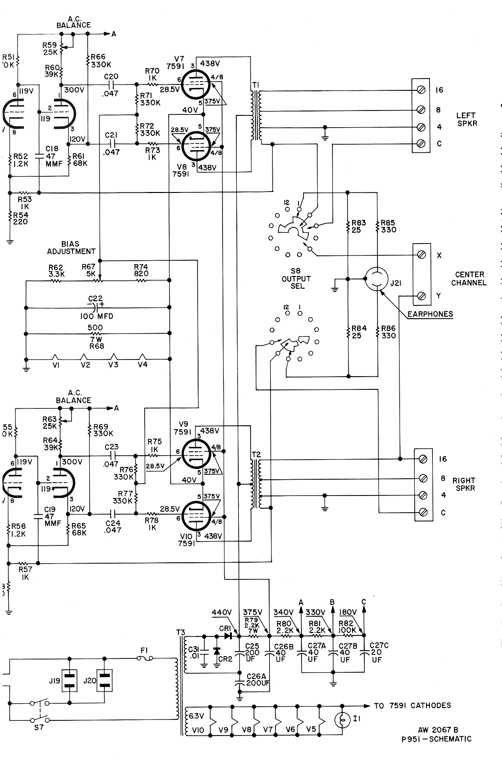
1. This is a cathode biased unit. There was voltage on the cathodes (pin 5) of the 7591s.
2. There's a bias pot but when I turned it, after marking its initial position, nothing happened. After messing with it a while, I flipped the amp up on its side and tried it again. From the schematic, it looked like some of the lower voltages on the preamp and amp tubes should be changing. Well, when I turned the pot from the top, it wasn't turning the wiper. I could tell because the inner plastic ring on the pot was not turning. So, I put a small flat bladed screwdriver into the hole from the bottom, turned that and was able to bias up the amp at the 7591s to within .2 volts of the recommended cathode voltage.
3. The more this amp ran, the better the voltages looked and the better it sounded as the caps relaxed in.

Here are some pictures. The output coupling caps picture shows the three pots. The two to the left of the picture are the phase inverter pots. I'm not touching those. The third one was the bias pot I had to adjust from underneath.

I have to say, I wasn't expecting a whole lot because the iron isn't the biggest, the power transformer has a mechanical hum, and the output transformers aren't the largest. This one's only rated for 60 watts. For now it's got generic preamp tubes in it and GE output 7591s, my least favorite, but even though, this amp sounds pretty amazing.

Now it's time for some tube rollin!:king:
 

Attachments

  • outputcouplers.jpg
    outputcouplers.jpg
    152.6 KB · Views: 194
  • undrchassisaftr.jpg
    undrchassisaftr.jpg
    147.2 KB · Views: 189
  • cancapstopsideaftr.jpg
    cancapstopsideaftr.jpg
    99.4 KB · Views: 163
  • 3switchtypes2.jpg
    3switchtypes2.jpg
    62.3 KB · Views: 142
Last edited:
Ok, now I've done the tube rolling.

Here's what I'm using:
Phase inverter positions: EH 12AX7s - recommended because of their spiral filaments and general robustness. Not a tone sensitive position as long as they pass full bandwidth.
Tone control positions: Sylvania JAN long pinched plate 12AX7s - Generally good tone and tons of gain
Preamp position - GE triple mica 5751. Thanks ke4mcl! I rolled a lot of tubes in this position including the following:
*Amperex Bugle Boy 12AX7 long plate Herleen code
*Mullard waffle plate 12AX7
*Sylvania JAN long pinched plate 12AX7s
*Westinghouse long black plate 12AX7s with square angled getter - some of my faves. Rare!
*Fisher Telefunken long smooth plate 12AX7s
*RCA triple mica black plate 5751
*GE triple mica black plate 5751
*Sylvania gold brand triple mica black plate 12AX7

The GEs win by a country mile. They're such underrated tubes. A waste in any position other than preamp stage positions though.
Maybe it's that my ears have grown used to them and I now prefer their sound. Not sure on that.

The outputs are Eico/Westinghouse 7591s. Thanks diamondsouled!

I got the last two Jensen copper foil in oil .22 uf caps for the tone control section. You can see a photo of the preamp section with all the expensive caps. Russian K40Y on outputs. Don't want to have all the same caps everywhere. Those Jensens are expensive, but once I got a line on the quality of this cathode biased amp, I figured ah what the hell. I'd bought a bunch from someone with good intentions and bad soldering iron skills for half his cost. I did have to buy those last .22uf caps, but it was still worth it all.

Sonics:
This is the most three dimensional, distinct sounding amp I've done so far. Not only does it image side to side, but front to back, with height information, and the bass is startling. At a thrift store the other day, I bought a vinyl copy of Joni Mitchell's "Don Juan's reckless daughter". Jaco Pastorious (sp?) plays bass. That mid-70s Jazz period is my favorite of her music. There was one song at the start of side 3 that when the bass came in I was genuinely startled. It just jumped out at me like it was in the room.

Looks: It's a fine looking piece.

For the extra curious, there are a couple pictures of it on page 11 from Saturday's winter doldrums fest. http://www.audiokarma.org/forums/showthread.php?t=272700&page=11. I'm the blurry guy.

The power transformer still has a mechanical buzz. If anyone has one that's an abandoned project or something comparable so I can get a replacement power transformer, I'd genuinely appreciate it.

I know that this amp will just improve as the caps all break in. They're at about the 30 hour mark now.
audiodon
 

Attachments

  • spensivecaps.jpg
    spensivecaps.jpg
    98.5 KB · Views: 138
  • finishedincase.jpg
    finishedincase.jpg
    57.9 KB · Views: 112
When I was in University a friend who was in EE spotted one crubside in the trash and knew enough to grab it. Since he knew I was into audio he gave it to me. It worked so it got used in various capacities such as main amp in my HT (well really sound for the TV) system. Never sounded close to as good as my X-202B but that is understandable given it has never been restored. Still have it, cool piece.

Interestingly, mine seems to have a non original volume pot as it does not have the on/off function and the unit must be shut off via the AC cord. Maybe it had the pot issue you describe above?
 
I removed and shellacked the transformer in a 24 hour bath, paying careful attention in putting it back together.

No difference in the sound.It still has that mechanical buzz. :cry:
 
Fishers are nice, the recent topics on Fishers spured me to rotate my restored 400 back into my system. I love the sound of my 400. There is just something about the vintage sound, smooth fatique free listening and adequate power.
 
I recently noticed something . . . or should I say I stopped noticing something. The power supply transformer buzz has diminished considerably through the last few weeks of use. With the X-101-C in a cabinet, the buzz has diminished enough to be tolerable. The fan on my laptop is louder now as is the whole house humidifier running on the bottom of the stairwell I can hear through a closed door.

So, I now consider the shellac bath worth it.
 
Nice work! I too love the styling and I'm a big fan of the 7591As.

I'm working on a X-101-C now. I'll post up a photo when the wife surrenders the camera. I was wondering if you measured your 7591A cathode currents? Mine seem too high (operating around 50ma, just beyond 100% power) and it has me a little concerned. Are your's operating that high?

I'd like to hear your take on my thinking and head scratching. It goes like this: The Sylvania data sheet for the 7591A calls out max plate at 85ma and max screen grid at 11ma (for a pair). Thats 48ma per tube at 100%; say 36ma at 75%. The cathode voltage spec is 40V and is adjusted with the bias control. The cathode current has two significant paths to ground: 1) across that long green 500R 7watt resistor and 2) the series filaments of the four 12AX7s operating at 10V each. Let's guess the series filament current is about 120ma (I should measure it directly). 40 volts across the resistor is 40/500 or 80ma. So the sum of those two paths at 200ma in total split across the four 7591s at 50ma each. That appears to match the 100% figure.

So, my conclusion is that Fisher designed this amp to work the 7591s at 100% power and about 40 watts per channel. Do you think that's correct? Does yours operate at this level? Is my thinking on the tube ratings flawed?

In short, I hate to operate those 7591As at that operating point. I'm thinking of changing the 500R resistor to 1600R to target a 36ma cathode current.

Please share you thoughts. I'm thinking those guys at Fisher knew what they we're doing. But again, they might not have cared about tube life as much as I do.

Thanks

Dave
 
Hi Dave,
My take on it is that since the X-101-C is cathode biased, the load is well balanced across the output 7591As. So, I'm thinking that you're right in a way, but you may be overthinking this.
My experience is that cathode biased units are much gentler on the output tubes than fixed biased units, even when the fixed bias system is biased at ~30ma.
I asked on the fishergroup one time about people's impressions of cathode biased units, because I like them sonically. Those who rely on theory over their own observations universally claimed the merits of a fixed bias architecture, but my ears tell me that I can do without that last 3dB of gain for the sonic quality and tube life extending qualities of a cathode biased system.
Do you have the 10 ohm resistors on your 7591A cathodes and have you measured each tube? That's how I set my bias to match as closely as possible between the two tubes in each pair. Between putting the most closely matched tubes together as a pair and then rolling the bias pot, I got them very close, even without a meter like a fixed bias KX-200 uses.

If anything, I think that the X-101-C's official rating is about 25 watts per channel. Going from recall now, most of that operation of a cathode biased amp is as a straight class A amp, falling into AB as higher power demands. This setup contributes to the outstanding microdetail, depth and wonderfully deep 3d soundstage of this amp since not everything is loud.

The Eico Stereo 40 is also cathode biased. I recall getting one that looked like it had been left on to heat the dog's house for years. It clearly had a lot of use but those 7591s tested like new and are probably my strongest and most evenly matched quad of 7591s.

I think the Fisher folks knew what they were doing too. In fact, I think this is one of their absolute best late-model designs. Mine will be with me until I can't hear anymore or someone inherits it from me.

I use old Westinghouse 7591As, and I don't worry about 'em one bit. Mine runs all day four days a week in my home office system.
 
Last edited:
This might be helpful to those interested in the above post.

page5.gif
 
Humm, How do you balance the output tubes between pairs? Is that with the A/C Balance pots. I should have another look at that. I though that was for hum.

I take it that you are operating around 50ma then.

Yes I do have cathode resistors, 1 ohm in this case. Part of my anxiety over tube longevity is justified because the fine RCA coin based tubes I'm using are suitably well matched as pairs but the two pairs differ greatly. One set is running at 40ma while the other is at 60ma. If this is adjusted with the A/C balance pots, then I can resolve this problem easily.

If that is what you are referring to?

I apperciate your help!

Dave
 
Last edited:
You know Dave,
I'm not a big concept guy. I'm much more physical in my approach. I know there are three pots on the back right of the X-101-C. Two say phase, and one says bias. I didn't touch the phase inverter pots, only the bias.

After I completely recapped my X-101-C, including all electrolytics and diodes as well as couplers, I loaded it with tester matched tubes, turned it on, played with the bias pot a bit and it was fine. My notes say the following after the recap:

With the unit on for four hours @ approximately 122.6 VAC:
Rail voltages:
CR1: 458 Expected 440
R79: 384 Expected 375
R80: 365 Expected 340
R81: 353 Expected 330
R82: 184 Expected 180

Output tube voltages
Grid 23.0
4+8 375
3 438
5 40

Bias on all four tubes
Between 38.6 and 43.7

V5&6
Pins 4-5 38
Pin 1 300
Pin 6 119
Filament drop ~11.6

V1-4
Pin 4&5 ~11.6
Pin 1 82 *V1&2 255 *V3&4
Pin 6 82 *V1&2 255 *V3&4
 
Ok, that's a big help to me. I have some problems I need to sort out. Your bias at -17v (23-40) and cathode currents are just what I had expected but I'm nowhere close. I need to keep troubleshooting. I'm not getting that much bias. Coupling caps would account for that but they all teated good last week. Time for another look.

I'd bet heavily that the AC balance pots are designed to allow you to get equal AC ripple on each leg of the OT even if the power tubes are not perfectly matched so as to cancel the hum. If your amp is not dead quiet, you might want to play with that. Just my $.02.

Thanks for taking time to respond.

Dave
 
Back
Top Bottom