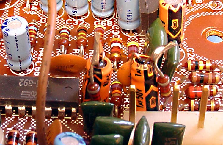
Folded over cap lead.

Dearslayer

Super Member
Pulled a working 2230 from the shelf tonight to start a recap on it, because I currently can't go any further on the Bias issue on the 2270 I'm working on till I place an order for more parts next week. Anyway I decided to start the recap at the PS on this unit. When I removed the cap at C804 I noticed the negative lead was folded over from the factory when installed and was not through the hole on the board. How could this thing work proper in this condition? Only noticeable abnormal condition about this unit is when powered on initially the display lights flicker slightly for a minute or so then it stabilizes and stops flickering. Other than that it seems to work just fine. Bare in mind I acquired this unit about 6 months ago and haven't had any extended listening time on it as it just sat on the shelf till tonight. It sure wasn't going anywhere with the amount of dreaded glue on it. Took a couple hours to clean and scrape all the glue off the board.

GT.
 

Attachments

  • image.jpeg
    image.jpeg
    43.4 KB · Views: 59
You can be sure it will have had some impact on hum specifications, but maybe not obviously or audible.

It gets its power from a filtered location already. Maybe you did have 2 or 5 times as much rubbish or so on the power regulator output, but 5 times almost nothing is still almost nothing....

If it was used for many years without complaints, it would be a good "proof" which brand or type of cap in there at that location really does not matter, if whether it is in or not is hardly audible. ;)
 
Looks to me like it was originally mounted OK - but someone took the capacitor out and didn't remount it properly, the folded lead is cut short - as if it has been in the board and OK at some point, don't you think?

Interesting find.
 
Looks to me like it was originally mounted OK - but someone took the capacitor out and didn't remount it properly, the folded lead is cut short - as if it has been in the board and OK at some point, don't you think?

Interesting find.

I'm no expert for sure, but it did look very much like the solder pad was original and undisturbed like all the rest on this unit. That's why I thought it a little odd. I remember watching a video on YouTube ( blue note repairs if I remember correctly ) where the guy found the exact same thing while recapping the power supply.

Maybe all the dang glue helped transmit the signal. Geeeez I hate trying to remove that stuff. I know once the lid is on nobody sees the internals but I hate putting scrape marks on the board trying to remove the old crap. Seems nothing really softens it up to remove easily.
 
Record the serial number for future postings. Maybe the factory made that modification on later units?????

There's a million of those 2230s out there. But maybe everyone just pulled it "assuming" it WAS connected???
 
Looks to me like it was originally mounted OK - but someone took the capacitor out and didn't remount it properly, the folded lead is cut short - as if it has been in the board and OK at some point, don't you think?

Interesting find.
maybe they cut them short before installing to save time ?
 
After trying many tools, I have found a sharp 3/8-1/2" wood chisel is the easiest way to get that glue off the PS board. You would think it would scratch, but if you keep the angle as low as possible and have it VERY sharp, it will take that stuff right off.with minimal scratching. that is the one board where I remove all of the caps at one time (with good records), so I can clean better. I've tried all of the solvents and none are satisfactory. Get it 99% clean with the chisel and then acetone or 91% isopropyl alcohol to clean the minor residue.
 
Funny you mention that because that is exactly what I had done is remove them all and I usually don't. I take Picts and make a very rough drawing and lay them in the apropiate spots on the drawing. Also use a sharpie to put a black mark on rack cap facing the front of the receiver. I will try the chisel method you described next time.
 

Attachments

  • image.jpeg
    image.jpeg
    65.1 KB · Views: 17
  • image.jpeg
    image.jpeg
    75.9 KB · Views: 17
Well gentlemen I think you are both correct. The pin does look like it was tinned however it feels smooth when running my finger over it. The other pin is rough from the solder that's left on there. I still don't understand how that could be, considering there's no way the glue was broken on any of the removed caps. The glue was as hard as glass with no breaks on all the ones I removed , and I would have noticed if one was tampered with at some point. I tried to get a better close up shot of it under the light.
 

Attachments

  • image.jpeg
    image.jpeg
    95.7 KB · Views: 16
Depending on the size of the part, it could have been an error by the "pick-and-place" machine, which would not "feel" that the leads did not both slip in smoothly. . Larger 'lytics were typically hand installed. Smaller 'lytics came on tape and reel, and the leads came more or less pre-formed, and all came pre-tinned. If the leads on this part got distorted some how, the pick and place machine would still try to push it in. This part could be right on the threshold of auto-placeable, if it is an error seen elsewhere with the same part.

Then, the boards were "wave-soldered." Unless the part is critical, and manifests significant issues, its being missing might not be caught, or show up noticeably at all.

Enjoy,
Rich P
 
See some weird stuff every now and then. Found these in my Sansui QRX 9001 when I did a restoration. It IS a factory mod ... pretty fly way to add a resistor they forgot ...

f2589-drop-resistors.jpg
 
Thanks for the explanation Rich. That does make a lot of sense but I thought that all caps and Semis " Had " to be placed correctly. I only say that because I've personally made my own rookie mistakes by putting something in backwards and things wouldn't work until corrected. Just yesterday after finishing the PS board I plugged the unit into the DBT and found that the bulb didn't dim. Shut it down right away to see if I could notice anything wrong visually and sure enough I had a Diode in backwards at H804. Oriented it correctly and it worked fine.
 
See some weird stuff every now and then. Found these in my Sansui QRX 9001 when I did a restoration. It IS a factory mod ... pretty fly way to add a resistor they forgot ...

f2589-drop-resistors.jpg


Wow that is a pretty funky way to install at the factory. I guess what the eyes don't see the heart don't feel.
 
Thanks for the explanation Rich. That does make a lot of sense but I thought that all caps and Semis " Had " to be placed correctly. I only say that because I've personally made my own rookie mistakes by putting something in backwards and things wouldn't work until corrected. Just yesterday after finishing the PS board I plugged the unit into the DBT and found that the bulb didn't dim. Shut it down right away to see if I could notice anything wrong visually and sure enough I had a Diode in backwards at H804. Oriented it correctly and it worked fine.
Some parts are not critical, and many 'lytics in a design are not. Frequently, they are for local decoupling, or additional smoothing, where they are downstream from much larger ones (compensating for increased spurious inductance in larger ones). Having one lead pressed flat, rather than pushed through the board results in the component being effectively missing, rather than backwards. Chips in wrong will generally get caught during board-level and end-assy-level testing. Of all of the parts in a design, many 'lytics could be missing and not cause noticeable issues. Some will definitely be missed, others, not so much

Enjoy,
Rich P
 
Back
Top Bottom