Getting the Most From Fisher FM Stereo MPX Tuners and Receivers

And it may in your location. My notes don't show that is does, as that remedy was developed after I serviced your unit.

Dave
 
I did my first dancing eye tube fix on this 400 today, and it certainly helped the problem, now I will do the same on my other units. I still get a bit of dance on weaker stations, but it is mostly gone. :thumbsup:
 
At some level of signal strength, some modulation will always become apparent. The modification does not completely eliminate the noise detector; it simply renders it less sensitive. As noise becomes completely unacceptable then, the eye tube will dance -- either due to the noise that the detector is responding to, or because AM is creeping into such a weak signal. I should mention that the values I gave are based on a properly operating, well aligned unit. As that becomes less and less the case, then the modification will have less and less effect. The values generally allow for a steady beam on virtually any usable signal, while if dancing is notable, then the station should display notable noise as well.

If you want to see how much of the remaining dancing is due to noise detector action, then simply short the modification resistor out temporarily. Then the noise detector will in fact be disabled. Any dancing remaining will then be due to the presence of AM due to the limiters being maxed out, or a less than optimum alignment of the set.

Dave
I'd say it's fine, I'm glad it was simple and easy for me. Thanks again for giving us Fish heads another great problem solver solution. Now if I can only master that individual bias modification, and EFB. Every time I sit and start to study it, something else comes up. :cool:
 
I've been playing around a bit with my TA-600 and the MPX unit I have. The MPX came from a 500B, and the only thing marked on top is "W". Not sure if thats the "WX" unit or what.

Going from the internal mono tuner to the MPX unit, I notice a drop in highs on the MPX. Not terrible, but enough that I need to bump the treble control. Reading over the bits about the de-emphasis network and it's various setups I'm thinking that mine don't match. The thing is, the particulars of this setup have me confused as to how to calculate the proper values.

This is the TA-600's network, with the stock values drawn in.

ta600_fm_network.jpg

This is the schematic for the MPX unit I'm using. Its pulled straight from the Fisher 500B manuals that I turned up online. C221/C222 are .02uf in mine, other values in the network do match.

Fisher MPX schematic_cropped.jpg


What has me confused is that there seem to be more steps in the network than Dave's description. Sounds like on later models this is one resistor and one capacitor? I'm fine with leaving the 600's network alone, but I'd like a wee bit more top end through the MPX decoder if I can. If someone would be kind enough to 'splain this to me I'd appreciate it muchly. I guess I could just monkey with values but I'd prefer to have it proper.
 
Gadget -- The de-emphasis networks at the output of the MPX subchassis is a two stage design that performs a combined function of providing the correct de-emphasis (75uS) within the audio spectrum, while also at the same time providing a pronounced null at 38 kHz to filter out any artifacts of the sub-carrier frequency. Obviously, the notch filter appears first but because its effect fall down into the audio spectrum, the actual de-emphasis network (the second part) is modified so that when used in conjunction with the notch filter, the proper 75uS de-emphasis is obtained at the output.

I checked response at the output of the MPX unit and compared it to that of a properly de-emphasized signal directly from the ratio detector, and as I recall, to the ideal curve as well. Ultimately, I found the output of the MPX unit to be pretty darn good -- certainly nothing to go changing values over, particularly if you want to keep 38 kHz artifacts our of your system.

Beyond that, I'm not sure I understand your question/comment about more steps in the network than my description. Could you please expound?

Dave
 
You mentioned one resistor and one capacitor, looking at my 600, it seems there are two "steps" in it, one is R52 and C68, the other is R58 and C70. Is this just a matter of calculating the two and adding it up ?

If the output of the MPX is how it should be, I'll leave it be then. I guess maybe the highs are a bit brighter than they should be on the internal tuner then. Maybe I'll swap the ceramic caps for something better.
 
When this equipment was designed, there was the 19 kHz pilot, 38 kHz subcarrier and maybe a 67 kHz SCA carrier. Today, some stations may also have a 57 kHz RBDS subcarrier that would be close to the 53 kHz upper limit of the 38 kHz subcarrier. Would these units benefit from having an additional filter at 57 kHz?
 
Gadget -- The output of the sub-chassis type MPX units of Fisher has always been a two step design. Now the mono de-emphasis network is a simple resistor and cap. Could you point me to the comments you are referring to that I made? If so, I'll see what context I was making them in.

Fred -- No doubt they would. But there is no analog filter I'm aware of that you could use to null at 57 kHz, without it serious impacting the upper side band (up to 53 kHz) of the stereo sub-carrier. As it is, Fisher recommends adjusting the 67 kHz trap to null at 80 kHz -- presumably to in fact make sure that the complete upper side band is passed un-attenuated. I believe it would take a digital filter to attenuate so close a frequency without affecting the upper side band.

Dave
 
Could you point me to the comments you are referring to that I made? If so, I'll see what context I was making them in.

The standard Fisher mono FM de-emphasis network consists of a 47K resistor, and a capacitor, ranging anywhere between .0015 uF and .0027 uF, with the varying cap values producing the various de-emphasis values used. The proper de-emphasis value is achieved by any combination of resistance in Ohms and capacitance in uF that has a product of 75.

Thats what I was confused on. Those values don't match whats in my TA-600's mono output.
 
Ah -- Thank-you! I was in fact referring to the mono de-emphasis network as stated, but I should have been clearer about the components used. Fisher did come to standardize the resistor value in the mono de-emphasis network in virtually every one of their stereo MPX tuners and receivers at 47K. But before that time, anywhere from 22K up to 33K and even slightly higher were common with the earlier units like the TA-600. Sorry for the confusion, and thanks for pointing it out!

Dave
 
ok so just for my sanity, do I work out the curve on the TA-600 by working out the constant of R52 and C68, and adding it to the value of R58 and C70? If so, that comes out to be .09 + 68 so 68.09 ? If 75 us is the right value, it looks like changing R58 to a 75K would put me there.
 
You're on the right track, except you disregard the 270 Ohm and 330 pF components (R52 and C68). Note that they appear before the MPX output as well. R52 assures than the output of Z4 cannot be loaded down excessively by anything connected to the MPX output jack, while C68 prevents any RFI from entering the set via the MPX connecting cable. Their effect on the audio and MPX signals is beyond nill as your math proved out.

The de-emphasis network in the TA-600 is a single stage network made up of R58 (68K) and C70 (.001 uF) for a time constant of 68 uS. You can either increase R58 to 75K for perfect de-emphasis, or increase C70 to 1100 pF for an accuracy within 0.27%.

Dave
 
awesome, thanks for letting me know I was on the right track. I have some 110pf caps, so I can just tack one of those in parallel with the existing 1000pf part. That should actually get me ever so slightly closer to ideal.
 
.....
As it is, Fisher recommends adjusting the 67 kHz trap to null at 80 kHz -- presumably to in fact make sure that the complete upper side band is passed un-attenuated.

AHA !!! In the 600-T, the 67 kHz trap is not adjustable and I was curious as to why it would resonate closer to 67 kHz with a 270 pF rather than the specified 220 pF capacitor. The 220 pF would put it up around 82 kHz. Thanks, Dave, for that bit of info. Wonder how many stations even broadcast SCA these days with streaming and satellite services being common.
 
3. Connect 22 uF 500V electrolytic cap between the connection of the 15K resistor/orange wire connection, and ground (negative to ground).

4. To ice the cake, I also change R123 to a 2.7K 2W resistor. This has nothing to do with the MPX tube change modification, but results in very normal supply voltages at the 350 volt and lower supply points, to help account for today's higher line voltages -- even when a current limiter is installed to help aid that effort as well.
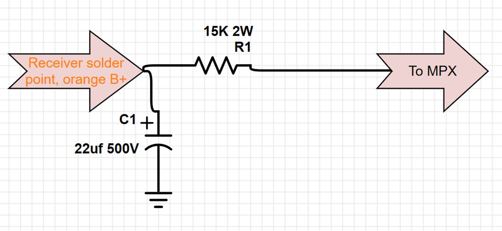
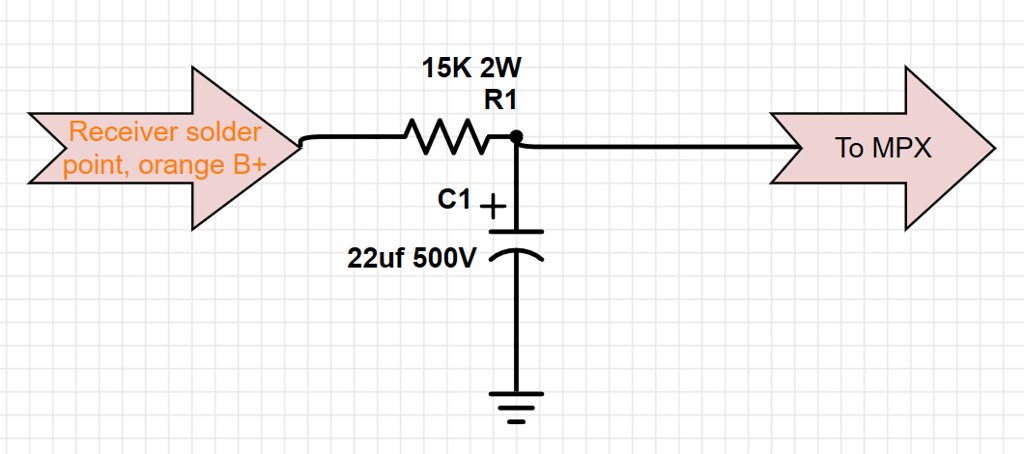
I have a question about these two steps regarding converting V100 and V102 to 12AT7s. I have the resistor and cap and am ready to install them in my 20xxx-series Fisher 400. On the 400 the orange B+ wire to the MPX chassis starts on a 4-point solder terminal. Would the positive lead of the cap be a) attached to the same point as the new resistor, or would it be b) attached to the resistor lead pointing toward the MPX chassis? I made a couple of simple diagrams to illustrate what I mean.

a)
36615461930_da81a7553a_b.jpg


b)
36615461970_6ca94ec8e8_b.jpg
 
RE: the 400 "dancing eye" tube fix

I took a look at the schematic for a late serial 400 and I want to verify what I would need to do.

To mitigate the dancing eye, does the recommended 47k resistor go where the red line is drawn in the below image? If not, please correct me. Thanks!!

IMG_4542.jpg
 
Back
Top Bottom