

Mark W.
Nut house of the Universe
Well this should be quite the thread. Along with the Stereo system, Rack and Speaker stands I'm sending my son I wanted to include everything
from Cables and interconnects to the OM and SM's for the units. This included a good indoor antenna. Since I am real happy with the modified
Cubic Quad I made following some instructions I found on the net 3 years ago I figured an upgraded and packable version of that antenna would suit
him well.
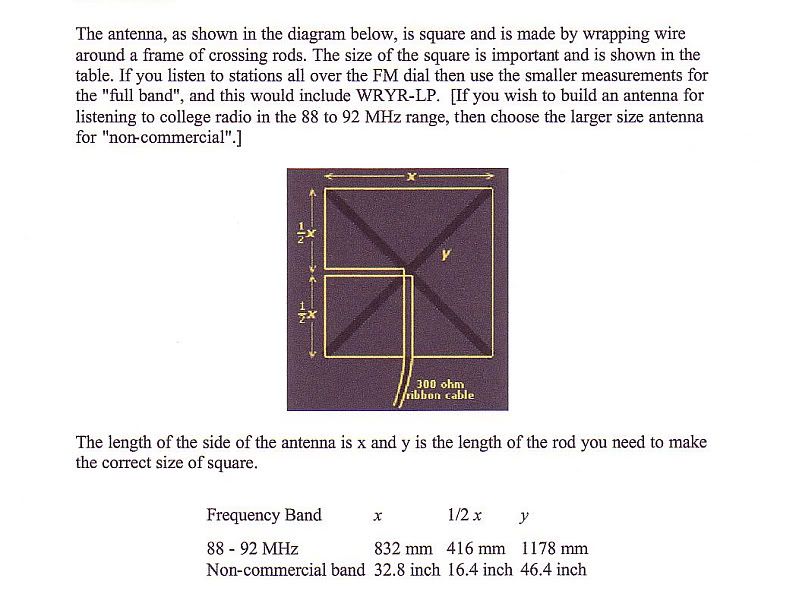
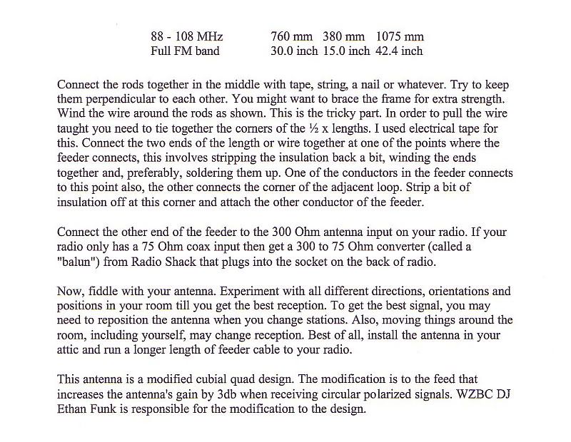
So here we go Instructions for a Mid Band Modified Cubic Quad antenna that at 30" square should cover the whole 88-108 band well with the highest gain
in the middle of the dial.
Should you only listen to the bottom of the dial you can lengthen the rods 2" and then figure the diagonal and lengthen them the proper amount.
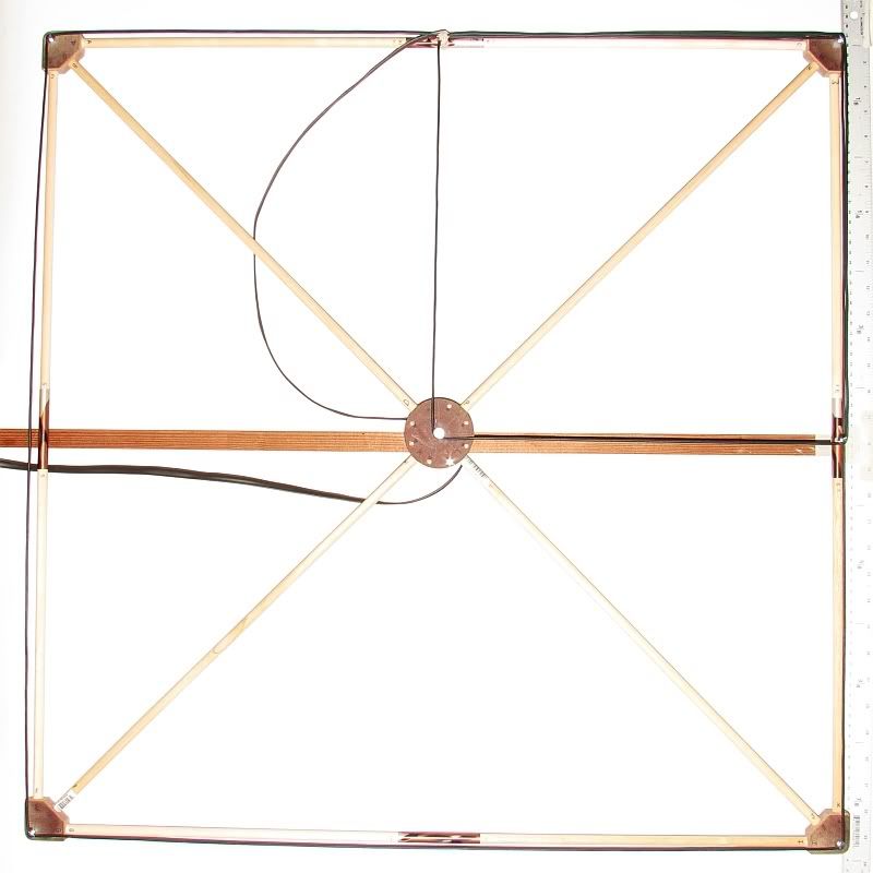
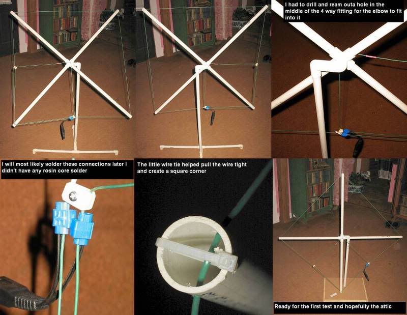
Here is how the antenna will look mounted to a wall or ceiling.
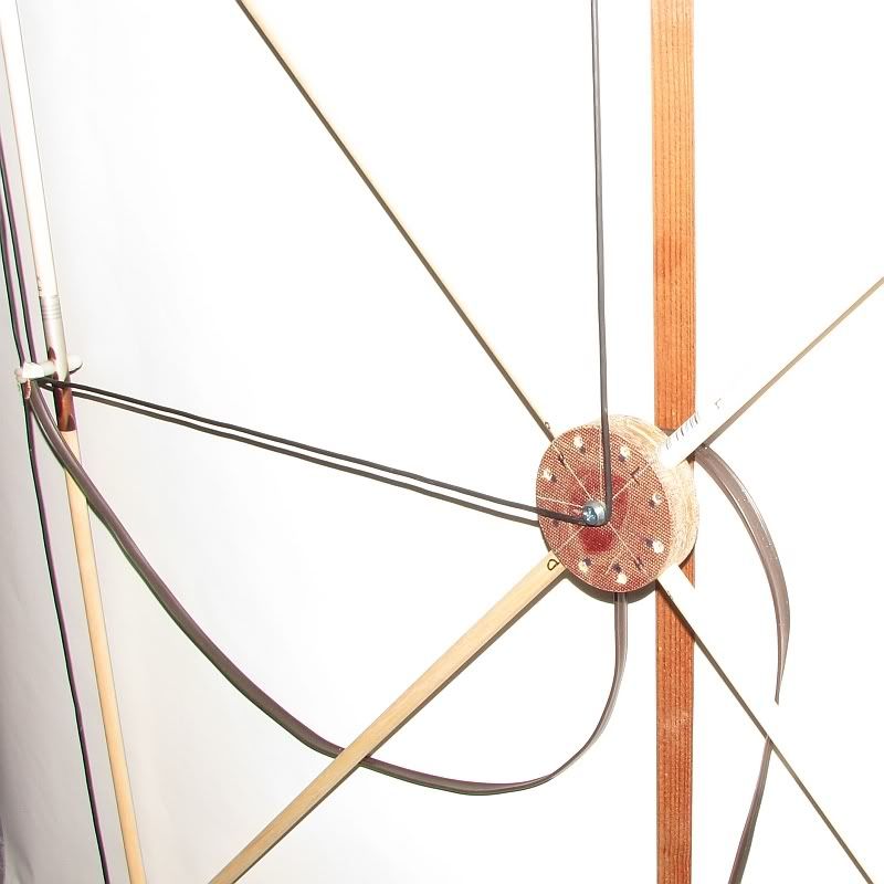
A close up of the center hub. Two of the holes seen in the Hub are not used and were part of an earlier design study. The lead in wire runs between a
spacer and a 1/4" dowel on the top side of the hub to allow the lead in to move as the antenna is rotated to point it in the best direction. So far I
have had great results with mine mounted flat to the ceiling in my office.
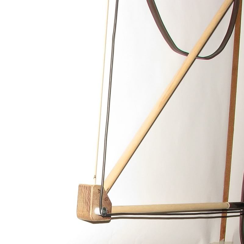
Close up of post number 5
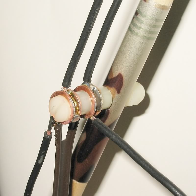
Close up of Post number 3 showing how the two levels of the wire passes around a corner.
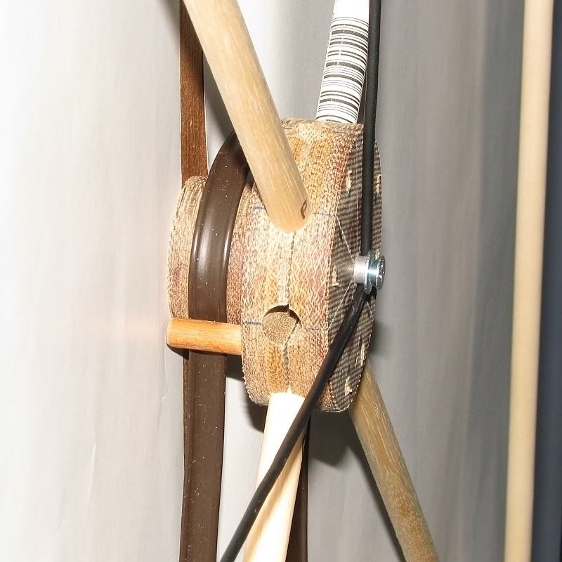
A view showing the 1/4" dowel that helps locate the lead in wire to the spacer it also shows how the wire is held in place in the center by the
washer and the long mounting screw.
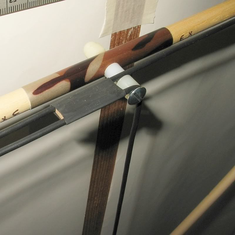
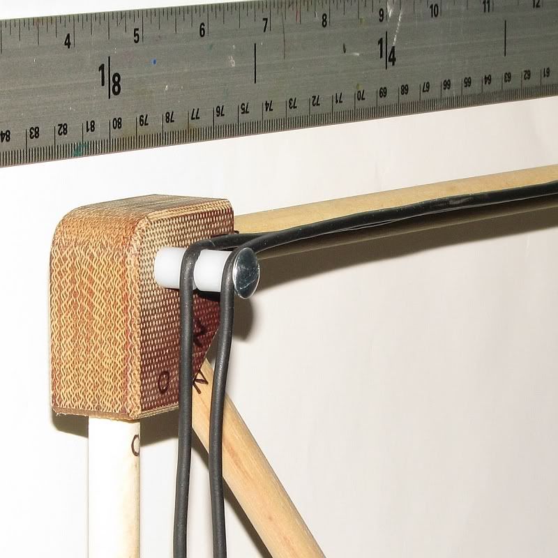
This photo shows the little wire spacer I made to help locate the wire back in place when it's removed for packing.
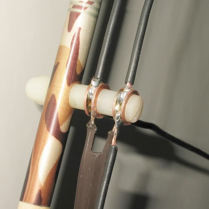
The above and below photos show close ups of post #4 where the splice and the lead in wire connects to the two squares. this should be done right at the corner. You can also see how
I used two copper washers to make a sandwich that holds the joints in place. Since my project is designed to break down and be moved in a box the size
the rest of his system fits into this helps orient the wire once removed.
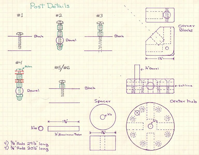
Parts drawings should you be nuts enough to make this the way I have. The 3/8" long rod lengths given on the drawing assume that you get the holes in the blocks to the accurate depth shown on the drawings.
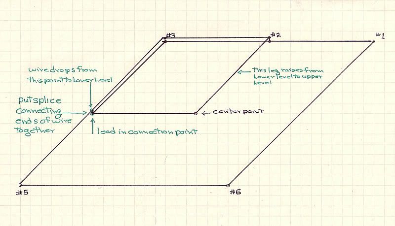
The wire routing I use.
OK random instructions and material lists etc.
Posts: (all 8-32 thread Pan head screws)
#1. Steel 0.75" L set to within 3/32" to surface of corner block.
#2. Steel 1.25" L with two 1/4" X 1/4" threaded spacers and Nylon acorn nut.
#3. Steel 1.25" L with two 1/4" X 1/4" threaded spacers.
#4. Nylon 1.375" L with two 1/4" X 1/4" threaded spacers and Nylon acorn nut.
#5. Steel 0.75" L with one 1/4" X 1/4" threaded spacer.
#6. Steel 0.75" L with one 1/4" X 1/4" threaded spacer.
Lead connection point is a sandwich the center being the antenna wire with the lead in wire
twisted around it. Then a #8 copper washer above and below the whole assembly being
soldered together while on the post. Nylon screw will handle the heat but should be replaced
with a new one as it will most likely bend. The upper lead in connection joint is also the splice
in the antenna wire so this is all soldered at one time. A 1/4" to 3/8" section of the lower
antenna wire will have to be removed to create a place for the lead in to be soldered to.
At a point just on the Post #3 side of Post #2 there is a 0.125" X 0.250 x 1.0 wood spacer set
between the antenna wires held in place by a 1" long piece of 3/8" 2-1 heat shrink tubing. A
note this has to put on the wire before the splice and lead in assemblies are soldered together.
Follow the drawing to see how to loop the wire.
The center of the antenna hub has a 1.625" long piece of .250 OD .025 wall aluminum tubing
the antenna wire loops around this as it's center post. A #8 washer is between the top of the
tube and the head of the #8 X 3" wood screw used to attach the antenna to the ceiling or other
support.
The splices or ferrules used to join the sections of the outside square of the antenna can be
omitted if the antenna does not need to collapse for shipping. I have not included those in the
drawings. The tubes I used were thin wall aluminum tubing from an arrow shaft. 3" long.
The holes for posts #2 and #4 are drilled with a #19 bit.
All 8-32 threads in the Phenolic used a #30 pilot drill Though in a harder material a #29 would
be called for and would work as well.
You will want as long of thread cutting 8-32 tap as you can find to have enough thread for the
screws.
Various Acrylic or materials like Delrin or Seaboard can be substituted for the Phenolic. Find
out if you can thread the material before committing to using it.
Oak or Maple hardwood can be substituted for the Phenolic material I used but you will have
to change the screws used at posts #1, #3, #5, and #6 for 3/4" long #8 steel wood screws.
You will need to pilot drill for these screws with a 3/32" drill bit. The nylon spacers used on
these posts will also need to be drilled out to remove the threads. You will have to set your
wire holding gaps by how deep you screw the wood screw into the corner block.
The center hub was made with a 2.5" hole saw that uses a 1/4" pilot drill you will need to do this
with a drill press to be accurate. The spacer was made with a 1.375 hole saw. A 1.25" would
also work. The center hub and the corner blocks are all made from 0.75" thick material.
The holes for the dowels were all drilled with a .375" spur point wood bit to achieve a nice deep
flat bottom hole. Be careful with you layout of the holes making sure to get the ones in the Hub
at 90 degrees to each other the ones in the center of the two corner blocks with three holes drill
real nice if you happen to have a V block to set them into while drilling since it will locate the 45
perfectly.
I used 8-32 flat head screws to hold the two halves of the center hub together and create the
clamp that holds the 4 supporting dowels in place securely. Drill the holes for these on either
side of each dowel holes about 1/4" in from the edge. I drilled with a #30 bit and then drilled
the 82 degree countersink just so the screw heads were a hair below flush.
After you have the 4 holes needed in the center hub you will need to cut the block into 2 halves
through the 0.75" dimension. This will then create the clamp to hold the supporting dowels in
place.
After the Center hub has been cut you can open up the screw holes with a #20 bit so the one
half does not get threaded. You can also go ahead and thread the other half of the center hub
at this time.
The whole antenna is designed to hang from a single #8 X 3" wood screw run into the wall or ceiling
should no stud or rafter be close by you can change this to some other form of mounting screw for
soft material. just be sure the spacer sits flat against the surface but not tight so to allow the antenna
to turn If you have a very textured ceiling you may have to either remove the texture of use something
like a piece of Ensolite foam or rubber washers to make up for the texture.
Tools required:
8-32 long tap
Tap handle
#29 or #30 drill bit
#20 drill bit
.375" Spur point wood drill
1.25" to 1.375" Hole saw w/1/4" pilot drill
2.5" Hole saw w/1/4" pilot drill
Drill press
V block
Bandsaw to cut the corner blocks though this can be done with a simple miter box and hand saw.
Sanding block and 120 grit paper.
Small miter box and saw to cut dowels to length (I used a hobby model sold by Xacto)
Soldering iron w/rosin core solder about 4"
Slotted and Philip's screw drivers medium and #2
Materials List
.075 X 4" x 8" Phenolic/Acrylic/Seaboard/Alder/ Maple/Oak/Delrin etc.
4) .375 X 36" Wood Dowels (could also be replaced with .375 carbon fiber or glass/epoxy
tubing)
2) .375 X 48" Wood Dowels " " "
Make sure all are as straight as possible and make sure they are a tight fit into a .375 hole.
40' coil of automotive 18ga twisted conductor wire
15'+ of 300 ohm twin lead TV antenna wire (you might need more depending on where your
antenna is to be located. This can also be replaced with a 75ohm matching Balum soldered at
the connection point and using a length of 75ohm lead in coax with an F connector on one end.
3) 8-32 X .075" steel pan head or larger head machine screws
2) 8-32 X 1.25" steel pan head or larger head machine screws
2) 8-32 X 1.25" Nylon pan head machine screws
8) 8-32 threaded 1/4" x 1/4" nylon spacers
2) 8-32 Nylon Acorn nuts.
7) 8-32 X .075" Steel Flat head machine screws
1" of 3/8" 2-1 heat shrink tubing
1" of 1/4" wood dowel or pencil etc. If using acrylic you could use that.
1/8" X 1/4" x 1" piece of wood ( a piece of a fudge bar stick would work)
4) # 8 Copper washers.
1) #8 X 3" steel wood screw
1) 3/16" fender washer
Should the WAF be important you can paint the frame to look nice. The wife and I also thought
that a light weight cloth or poster could be cut to fit on the bottom of the antenna to hide it if
mounting on a wall or ceiling.
I found everything I needed to make this antenna at out local ACE hardware store except the
Phenolic So if what ever you use for the blocks and center hub you will have to source.
I would not use MDF as it splits to easy and would be a poor choice to try to drill into the edge.
This is only the most complicated way to make this antenna I could come up with so you might
find a much simpler way of doing it. The first one I made used 3/4" Sch 20 PVC pipe and fittings
for the frame. I use the coax type lead in on that one and it works very well. I have a link to the
photo's of that antenna.
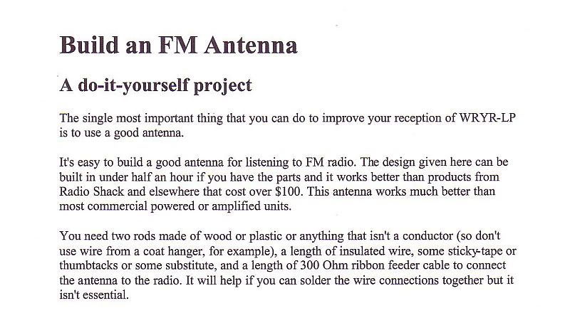
I have included the original instructions for this antenna I found on the Internet. Most of the drawings and photo's are gone but it might help. (A note here the wire path drawing in these instructions does not work well so disregaurd there was orginally two more drawings that showed how to string the wire that have been lost.
from Cables and interconnects to the OM and SM's for the units. This included a good indoor antenna. Since I am real happy with the modified
Cubic Quad I made following some instructions I found on the net 3 years ago I figured an upgraded and packable version of that antenna would suit
him well.
So here we go Instructions for a Mid Band Modified Cubic Quad antenna that at 30" square should cover the whole 88-108 band well with the highest gain
in the middle of the dial.
Should you only listen to the bottom of the dial you can lengthen the rods 2" and then figure the diagonal and lengthen them the proper amount.
Here is how the antenna will look mounted to a wall or ceiling.
A close up of the center hub. Two of the holes seen in the Hub are not used and were part of an earlier design study. The lead in wire runs between a
spacer and a 1/4" dowel on the top side of the hub to allow the lead in to move as the antenna is rotated to point it in the best direction. So far I
have had great results with mine mounted flat to the ceiling in my office.
Close up of post number 5
Close up of Post number 3 showing how the two levels of the wire passes around a corner.
A view showing the 1/4" dowel that helps locate the lead in wire to the spacer it also shows how the wire is held in place in the center by the
washer and the long mounting screw.
This photo shows the little wire spacer I made to help locate the wire back in place when it's removed for packing.
The above and below photos show close ups of post #4 where the splice and the lead in wire connects to the two squares. this should be done right at the corner. You can also see how
I used two copper washers to make a sandwich that holds the joints in place. Since my project is designed to break down and be moved in a box the size
the rest of his system fits into this helps orient the wire once removed.
Parts drawings should you be nuts enough to make this the way I have. The 3/8" long rod lengths given on the drawing assume that you get the holes in the blocks to the accurate depth shown on the drawings.
The wire routing I use.
OK random instructions and material lists etc.
Posts: (all 8-32 thread Pan head screws)
#1. Steel 0.75" L set to within 3/32" to surface of corner block.
#2. Steel 1.25" L with two 1/4" X 1/4" threaded spacers and Nylon acorn nut.
#3. Steel 1.25" L with two 1/4" X 1/4" threaded spacers.
#4. Nylon 1.375" L with two 1/4" X 1/4" threaded spacers and Nylon acorn nut.
#5. Steel 0.75" L with one 1/4" X 1/4" threaded spacer.
#6. Steel 0.75" L with one 1/4" X 1/4" threaded spacer.
Lead connection point is a sandwich the center being the antenna wire with the lead in wire
twisted around it. Then a #8 copper washer above and below the whole assembly being
soldered together while on the post. Nylon screw will handle the heat but should be replaced
with a new one as it will most likely bend. The upper lead in connection joint is also the splice
in the antenna wire so this is all soldered at one time. A 1/4" to 3/8" section of the lower
antenna wire will have to be removed to create a place for the lead in to be soldered to.
At a point just on the Post #3 side of Post #2 there is a 0.125" X 0.250 x 1.0 wood spacer set
between the antenna wires held in place by a 1" long piece of 3/8" 2-1 heat shrink tubing. A
note this has to put on the wire before the splice and lead in assemblies are soldered together.
Follow the drawing to see how to loop the wire.
The center of the antenna hub has a 1.625" long piece of .250 OD .025 wall aluminum tubing
the antenna wire loops around this as it's center post. A #8 washer is between the top of the
tube and the head of the #8 X 3" wood screw used to attach the antenna to the ceiling or other
support.
The splices or ferrules used to join the sections of the outside square of the antenna can be
omitted if the antenna does not need to collapse for shipping. I have not included those in the
drawings. The tubes I used were thin wall aluminum tubing from an arrow shaft. 3" long.
The holes for posts #2 and #4 are drilled with a #19 bit.
All 8-32 threads in the Phenolic used a #30 pilot drill Though in a harder material a #29 would
be called for and would work as well.
You will want as long of thread cutting 8-32 tap as you can find to have enough thread for the
screws.
Various Acrylic or materials like Delrin or Seaboard can be substituted for the Phenolic. Find
out if you can thread the material before committing to using it.
Oak or Maple hardwood can be substituted for the Phenolic material I used but you will have
to change the screws used at posts #1, #3, #5, and #6 for 3/4" long #8 steel wood screws.
You will need to pilot drill for these screws with a 3/32" drill bit. The nylon spacers used on
these posts will also need to be drilled out to remove the threads. You will have to set your
wire holding gaps by how deep you screw the wood screw into the corner block.
The center hub was made with a 2.5" hole saw that uses a 1/4" pilot drill you will need to do this
with a drill press to be accurate. The spacer was made with a 1.375 hole saw. A 1.25" would
also work. The center hub and the corner blocks are all made from 0.75" thick material.
The holes for the dowels were all drilled with a .375" spur point wood bit to achieve a nice deep
flat bottom hole. Be careful with you layout of the holes making sure to get the ones in the Hub
at 90 degrees to each other the ones in the center of the two corner blocks with three holes drill
real nice if you happen to have a V block to set them into while drilling since it will locate the 45
perfectly.
I used 8-32 flat head screws to hold the two halves of the center hub together and create the
clamp that holds the 4 supporting dowels in place securely. Drill the holes for these on either
side of each dowel holes about 1/4" in from the edge. I drilled with a #30 bit and then drilled
the 82 degree countersink just so the screw heads were a hair below flush.
After you have the 4 holes needed in the center hub you will need to cut the block into 2 halves
through the 0.75" dimension. This will then create the clamp to hold the supporting dowels in
place.
After the Center hub has been cut you can open up the screw holes with a #20 bit so the one
half does not get threaded. You can also go ahead and thread the other half of the center hub
at this time.
The whole antenna is designed to hang from a single #8 X 3" wood screw run into the wall or ceiling
should no stud or rafter be close by you can change this to some other form of mounting screw for
soft material. just be sure the spacer sits flat against the surface but not tight so to allow the antenna
to turn If you have a very textured ceiling you may have to either remove the texture of use something
like a piece of Ensolite foam or rubber washers to make up for the texture.
Tools required:
8-32 long tap
Tap handle
#29 or #30 drill bit
#20 drill bit
.375" Spur point wood drill
1.25" to 1.375" Hole saw w/1/4" pilot drill
2.5" Hole saw w/1/4" pilot drill
Drill press
V block
Bandsaw to cut the corner blocks though this can be done with a simple miter box and hand saw.
Sanding block and 120 grit paper.
Small miter box and saw to cut dowels to length (I used a hobby model sold by Xacto)
Soldering iron w/rosin core solder about 4"
Slotted and Philip's screw drivers medium and #2
Materials List
.075 X 4" x 8" Phenolic/Acrylic/Seaboard/Alder/ Maple/Oak/Delrin etc.
4) .375 X 36" Wood Dowels (could also be replaced with .375 carbon fiber or glass/epoxy
tubing)
2) .375 X 48" Wood Dowels " " "
Make sure all are as straight as possible and make sure they are a tight fit into a .375 hole.
40' coil of automotive 18ga twisted conductor wire
15'+ of 300 ohm twin lead TV antenna wire (you might need more depending on where your
antenna is to be located. This can also be replaced with a 75ohm matching Balum soldered at
the connection point and using a length of 75ohm lead in coax with an F connector on one end.
3) 8-32 X .075" steel pan head or larger head machine screws
2) 8-32 X 1.25" steel pan head or larger head machine screws
2) 8-32 X 1.25" Nylon pan head machine screws
8) 8-32 threaded 1/4" x 1/4" nylon spacers
2) 8-32 Nylon Acorn nuts.
7) 8-32 X .075" Steel Flat head machine screws
1" of 3/8" 2-1 heat shrink tubing
1" of 1/4" wood dowel or pencil etc. If using acrylic you could use that.
1/8" X 1/4" x 1" piece of wood ( a piece of a fudge bar stick would work)
4) # 8 Copper washers.
1) #8 X 3" steel wood screw
1) 3/16" fender washer
Should the WAF be important you can paint the frame to look nice. The wife and I also thought
that a light weight cloth or poster could be cut to fit on the bottom of the antenna to hide it if
mounting on a wall or ceiling.
I found everything I needed to make this antenna at out local ACE hardware store except the
Phenolic So if what ever you use for the blocks and center hub you will have to source.
I would not use MDF as it splits to easy and would be a poor choice to try to drill into the edge.
This is only the most complicated way to make this antenna I could come up with so you might
find a much simpler way of doing it. The first one I made used 3/4" Sch 20 PVC pipe and fittings
for the frame. I use the coax type lead in on that one and it works very well. I have a link to the
photo's of that antenna.
I have included the original instructions for this antenna I found on the Internet. Most of the drawings and photo's are gone but it might help. (A note here the wire path drawing in these instructions does not work well so disregaurd there was orginally two more drawings that showed how to string the wire that have been lost.
 Seriously a very nice detailed write up. I think it is great to see a Dad supporting his son this way. Our troops need to know we appreciate what they are doing and this is a good example. I'll be watching to see how it performs. Good on you Mark! :thmbsp: