

You are using an out of date browser. It may not display this or other websites correctly.
You should upgrade or use an alternative browser.
You should upgrade or use an alternative browser.
ka-6000 and kt-7000 in tha house, time to restore
- Thread starter bktheking
- Start date
Blue Shadow
Waiting for Vintage Gear from this century
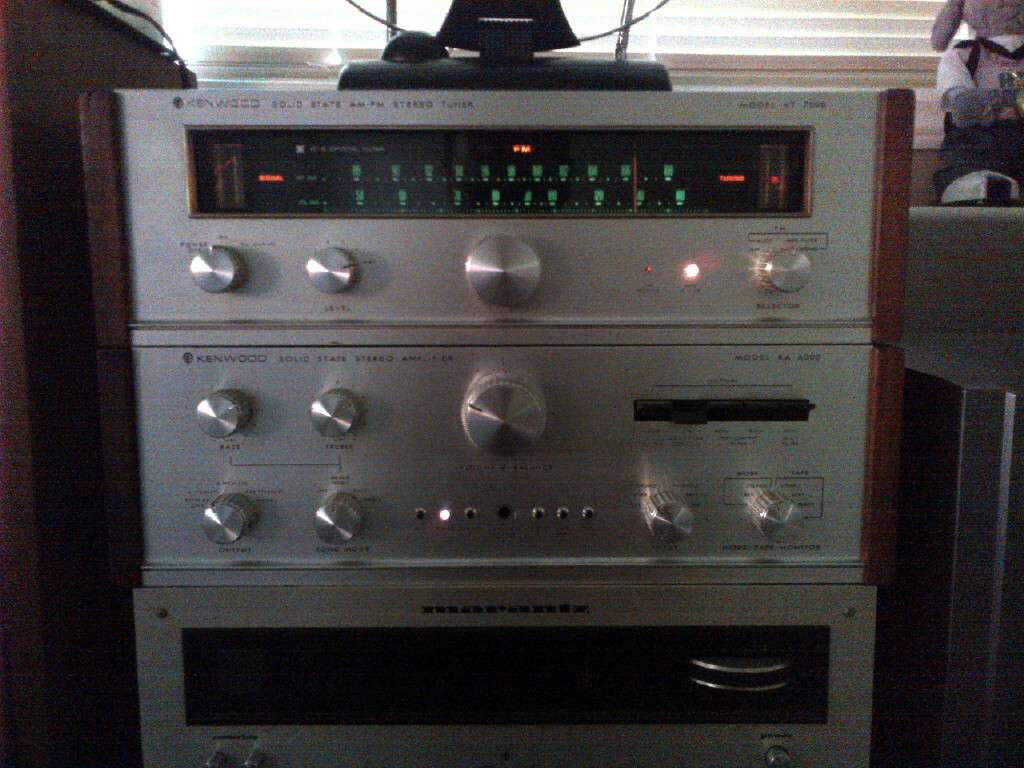
Do you have the side panels for those units? They sure dress em up without being too much wood. It also fills in the sides so there are only small gaps between them when stacked. Just like the feet put the faceplates close.

Blue Shadow
Waiting for Vintage Gear from this century
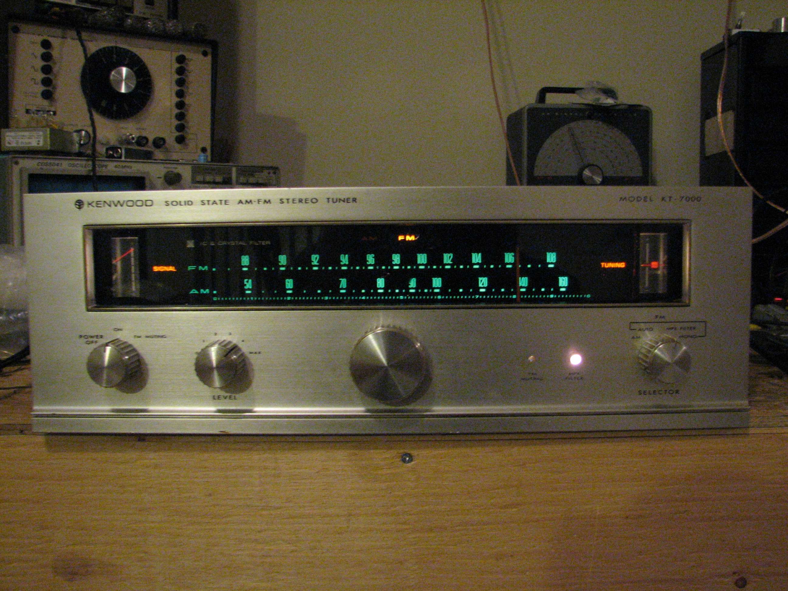
Did you swap the jewel lamps indicator lamps on the KT from the blue? Blue Shadow wants to know. Could be just the pic showing them as a reddish color.
Nice to see the pair looking good again and playing nice. Good signal strength, center tuned and stereo indicator light up. Can't get much better than that.
Nice to see the pair looking good again and playing nice. Good signal strength, center tuned and stereo indicator light up. Can't get much better than that.
 . That might be what you are seeing, reflection through the hole.
Blue Shadow
Waiting for Vintage Gear from this century
That explains why it is such a small dot of color.
I don't know how they blue blob of plastic is attached but maybe someone has a parts unit with a messed up faceplate. I know I used to, back in about 1980. The dial of that tuner was in horrible shape by then. I bought that one used to replace one I bought new and it finally died and I took it apart before I had the skills to fix it, not that I have those skills now. Gave it to a friend.
I don't know how they blue blob of plastic is attached but maybe someone has a parts unit with a messed up faceplate. I know I used to, back in about 1980. The dial of that tuner was in horrible shape by then. I bought that one used to replace one I bought new and it finally died and I took it apart before I had the skills to fix it, not that I have those skills now. Gave it to a friend.
lha1992
Kenwood Collector
Soo i'm working on my KA-6000 again and i desoldered some wires off mine on the board that sits infront of the power-supply caps next to the big coke can capacitor (you know the one that sits under that little black shield box).
Do any of you have a picture of how the wires are soldered to the back of that PCB board by any chance??
My 6000 is almost done so. Replaced alot of those ugly big film caps with modern ones and cleaned up the wiring. Just waiting for my friend Will (sir.byrd) to finish helping me with making a case for the 2 2200uf 100v caps that will replace the big coke can one.
bktheking
Gitter Done!
Why not just cut the can and use it to house the replacement caps. Post 12 shows the spot where the wires are soldered, that is one side in the pic, the other side is the same spot one the board, just follow the trace, the runs are a mirror image. If you need a clearer pic I can get one, just means I have to take it all apart again.
I think you will be happy with the sound, I have mine running Dynaco a25's.
I think you will be happy with the sound, I have mine running Dynaco a25's.
lha1992
Kenwood Collector
Why not just cut the can and use it to house the replacement caps. Post 12 shows the spot where the wires are soldered, that is one side in the pic, the other side is the same spot one the board, just follow the trace, the runs are a mirror image. If you need a clearer pic I can get one, just means I have to take it all apart again.
I think you will be happy with the sound, I have mine running Dynaco a25's.
Me and Will were going to do that but since everything is new in there why not just go for something a little nicer. He's going to be cutting a piece of wood to house the new caps in so it will have a little something different.
Also, the board in post 12 isn't the one i'm talking about, its the board infront of that one that is housed in its own little box that has the wires going through the chassis.
lha1992
Kenwood Collector
OK got ya, I'll shoot some pics for ya.
Thanks man!!!!
lha1992
Kenwood Collector
Here is the adaptor I made for the 63mm cap, will be replaced with two 25mm caps
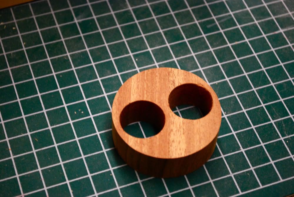
That is gonna look nice in the 6000 when its all done!!! Thanks my friend!!
Similar threads
- Replies
- 7
- Views
- 3K
- Replies
- 5
- Views
- 351
- Replies
- 6
- Views
- 5K