Kenwood KA-7300 - unsuccessful refurb.

Tonight I fabricated that pair of test leads with mini grabbers at both ends, jumped pins 13 to 22 and 19 to 20 but no difference. Still 1 weak & 1 strong channel plus the radio station.

Kind of grasping a straws but is it worth replacing that new capacitor I installed at Ci5, the one that increases gain of the radio station when touched? Perhaps it is defective?

My understanding is that a capacitor's voltage rating is generally inconsequential. Although the SM listed 50V 1mF at Ci5 what I installed was 100V 1mF. I have no more of those on hand but I do have 63V 1mF.
 
There should ALWAYS be a difference between them of about 0.6V (either positive or negative, depending on PNP or NPN). Anytime you see anything other than that, it should raise an eyebrow (bad supply voltages or dead transistor).
With this in mind, take a look at the last voltage measurements you posted.

Also, consider that the collector of Qi3 and Qi4 is tied directly to the -14V supply so measuring anything other than that requires an explanation as to why...

You are also reporting voltages that are totally different than what you reported earlier (emitter of Qi1 & Qi2 should = base of Qi6 and Qi5).

Ci5 and Ci6 is an important signal carrying capacitor, and something of quality should be used here. A 1uf or 2,2uf is fine here, as well as any voltage rating from 25V to 63V. I use stacked film caps, but for someone buying locally that's probably not going to happen.
 
I'm composing this on my phone so due to it's spell check, regrets for any grammatical errors.

I did not arrive home until 10PM last night so was without time to do anything. Instead I got up at 3:30AM to re-measure those transistor voltages. I previously used a probe on the foil side but sine you commented on the inconsistency, I wished to take them again. Thinking it may provide a better connection than the DMM's probe did, I placed one of those mini grabbers on the transistor's legs.

Some new readings were similar but some were not and I'm still unsure if they are correct. That bring so, I will move everything someplace better illuminated which will also allow better access to the board's surfaces than I have now.

As long as my workday does not exceed 15 hours today, I will remeasure again this evening.

In case their needed I did locate 63V 1mf stacked film capacitors. It was not the same vendor I use (they were out of stock) but another. The are film type and I assume they are stacked because of the box like appearance. I was not familiar with the term stacked film but looking that up produced images of box style capacitors.
 
Not to butt in, but you didn't specifically say if you used RCA cables connected from pre-out to main-in on each channel to bypass the norm/sep switch on the back panel.
 
Pretty sure we've isolated it to a preamp issue, but TBH this thread has gone on for so long I'd not swear to anything.

I was not familiar with the term stacked film
Stacked film is just a way to get a reasonable amount of capacitance in a relatively small space (compare a 1uf 63V stacked film with a 1uf 250V metallized polypropylene). Downside is available voltage ratings stop at about 100V. For most SS work, that's fine.
 
Yes, RCA jumpers were used and as EW mentions this current problem does not involve the power amp.

There are were/are also factory jumpers in the in/out jacks.
 
Instead of using a probe on the foil side of the board as I had before, for these readings I used one of those mini grabbers directly on the transistor's legs. To start, what I obtained on Q5 & Q6 were not the ideal numbers you specified
C: 0v E: 10.9v B: 10.3v

What I got were for Q5
C: minus 136mv E: +3.11v B: +3.7v
Q6
C; +4.45v E: minus 14.5v B: minus 13.9V

Those for Q1 to Q4

Q2
E: + .580v C: minus 13.85v B: + 6.6mv
Q4
E: +.579v C: minus 17.1v B: +137.7mv
Q1
E: +.573v C: minus 13.5v B: +38.6mv
Q3
E: +.573v C: minus 17.12v B: +93.1mv

Just so I'm clear on this, the DMM should be set at DC volts in this instance and not the diode setting?

I agree this thread has dragged on a long time and my foobars did not help. I am starting to have growing regret about interfering with the original owner's plan of taking it to the recycler.
 
HEY ! Don't give up now, just think when it's fixed you'll have accomplished
something and gained much knowledge. :music: Takes time. hang in there.

John M
 
Just so I'm clear on this, the DMM should be set at DC volts in this instance and not the diode setting?
Yes!

Supply voltages still good? By that I mean the voltage at the 'top' side of Ri16 and Ri26 (same for Ri15 and Ri25)...

Negative supply is tied directly to the collector of Qi3/Qi4, and is a bit high, but at this point it's moot. Why not just shotgun it? New caps for that section, and six new transistors...
 
I'll re-check voltages at those spots you point out.

Re shotgunning - myfeelings exactly, I shall do exactly that. And it will be ALL capacitors, even the electrolytics I recently installed. Plus I shall use those 1uF stacked film in position Ci5 & Ci6.

Will post again when done.
 
You will need to take great care installing the new transistors, so that the proper pin goes to the proper spot. Do not assume that the new transistor has the same pinout as the original. And I still recommend the service manual from Rick.
 
I was kept very busy yesterday and had no opportunity to get any parts. All I've been able to do since last posting was replace all of the transistors (on this half of the control board) and install those 1uF stacked film capacitors at Ci5 & Ci6.

According to data sheets, the 2SA970 transistors I used have the same pinout as the 2SA640 (which the factory used instead of 2SA763). I installed them as per the hole markings on the foil side of the board. Except I may have screwed up on Q11 & Q12. I say that because the foil side at those positions did not have holes marked ECB. When I pulled Q11 I failed to note how it was oriented because I expected its holes to be marked (as were all the others) but this was not so. All I can determine is that Q11 & Q12 share a Collector connection but since that's the center leg, I figure my chances of having gotten it right are 50/50. Both transistor housings are "facing" in the same direction.

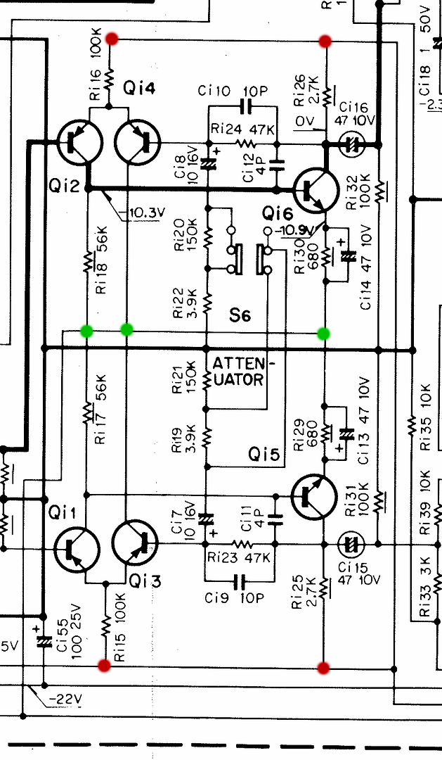
Regarding voltage measurements at R16 & R26 / R15 & R25:

R16 & R15 are horizontal so I was unsure what was the "top side" which you referred to so I took measurements on both sides. A little over 9 volts on one end and about .570 volts at the other.
R26 & R25 seem to be nonexistent. There is a position silk screened R25 but it is vacant and I could not find R26 marked anywhere on the board.

What may or may not be relevant is when I connected the mini grabber to R15, I heard the radio station and the volume control was down to off. .

Despite what I've done thus far, new transistors and two 1uF stacked film caps, nothing has changed. Still a weak left channel yet strong on the right but accompanied by the radio station whenever I touch the volume control.

If you think it worthwhile, I shall continue with replacing all the capacitors on the board as soon as time will allow and I can get to the parts store.

At the top, I mentioned this half of the board. There is also the other half - the tone control half. Since installing new electrolytitcs on it, I have paid it no further attention.
 
I thought all we were concerned with at the moment was the first stage of that control amp (Qi1 ~ Qi6). I'd have not messed with the rest of the preamp at this time. My impression was that the whole problem was getting a signal out of this first stage. I did not want to complicate this whole deal by adding more variables.

Many of the 'resistors' are not traditional resistors. Kenwood has quite a number of 'printed' resistors on this board, which are simply carbon tracks laid down onto the PC board (which is double-sided as well). I guess I'm fortunate that I've not had to troubleshoot this board in detail. A faulty printed resistor would mean finding a way to disable the original and bypassing with a traditional device. Anyway, the printed resistors are shown with the line under the device symbol.

Here's the supply points I was interested in...the red dots are supposed to be around +14V, and the green around -14V. By 'top', I was referring to where the +14V came in.

Ctrl_Amp_Input_Stage_zpss9tbq0hw.png~original
 
Last edited:
I woke up after 4 hours sleep so stayed up to take those measurements. Unfortunately it will take me more time than I have this morning, I only managed 3 so that will be my next post. I have to say that I have a hard time reading yellow graphics on a white background which is how those printed resistors are labeled.

You mentioned this was a double sided board. Are there pass through connectors going through the trace holes?

I was wondering if there was a possibility of my pulling some out when I removed the original electrolytic capacitors. That recently happened to me while changing relays on an aftermarket DC protect board in a power amplifier. I was unaware they were there and used too much force extracting it's pins.
 
Are there pass through connectors going through the trace holes?
My copy of the foil layout is so horrible that I really can't tell. Rick has the manual and states the overall quality is 'very good to excellent', but I bet the foil layout for the control amp is still going to be a pain to read. Still, it has to be light-years better than what I have. I'd not hesitate to get it if I thought it would help.

http://www.stereomanuals.com/man/rep/kenwood/kenwood_manuals_ka-1000_xx.htm
 
I just requested Rick send me a PayPal invoice for the manual. I started the process a couple of days ago but got annoyed because PayPal will not let me add the "Ship To" address I have in Sumas, WA for US purchases which is cheaper and faster. I can have stuff sent there I buy with PayPal on e-bay but not with them directly.

So I guess proceeding further should be delayed until arrival of the manual. Hope it does not take too long as I would like to re-claim use of my dining table and I don't want to forget things..
 
I received Rick's service manual yesterday but I woke up sick as dog this morning - 101 degree temp as of right now. Still need to put in my 15 hours or so at the job but it's in truck cab so not really able to infect anyone, just sweat and feel like crap.

This upcoming weekend I hope to pick up where I left off and will post what readings I get at the above measurement points.
 
Here are the supply point voltages you were interested in:

top red left: +.574 volts
top red right: +9.3 volts

left green: -15.0 volts
middle green: -15 volts
right green: -12.5 volts

bottom red left: +9.2 volts
bottom red right: +9.2 volts

Quite a deviation for the "reds" from -14 volts.
 
You'll note that the 'groups' are all on the same electrical potential...there's no reason for them to be different. Wrong reading, I'll buy. Different reading, nope.

Power down, discharge the caps, and get a resistance reading to prove that those 'groups' are essentially an equal-potential point.
 
Back
Top Bottom