Kenwood KR-7600 -- HELP!!!

Quick question...just to make sure I'm doing this correctly: the proper method for setting the bias voltage on the 7600 is to connect leads at pins 6 & 13 (16 &23) then adjust the corresponding variable resistor until it reads 40mV. Is this correct?

I'm trying to keep it around 38/39mV just to be safe and leaving it on for a while to warm up and get an accurate operational reading. Just wanted to make sure I'm not missing something here, that's all the SM has to say on the subject.

Yes that's right. The difference between 36 and 40 isn't a very big deal....
 
Yet more fun :) I keep blowing resistors at Rk1. Replaced it with a 100ohm yesterday, worked fine last night and earlier this morning. Came home, switched it on and off a couple times as I checked the bias, relay clicked, everything was good. Shut it off and put the top and bottom back on, once again Rk1 smokes out. Brand new resistor.

I have a couple new 56ohms and one more 100ohm to replace with, but does anybody have an idea what would cause this to keep blowing that resistor out? If I can track down what's causing that, I will finally have this thing done! I'm leaning that Rk2 could be out of tolerance and keeping Qk1 from turning on, thus holding too much voltage at Rk1 and causing it to short. Thanks again as always!
 
Last edited:
It does not appear that the Qk1 heatsink makes contact with anything else, so insulating it from the collector tab does not appear to be necessary. You're the man on the spot, so you'll have to determine if this is truly the case.

I assume you're replacing these resistors with 2W jobs? If that's the case, then there's an awful lot of current here unaccounted for. For a 56 ohm 2W resistor to burn up requires well over 200mA of current. For a 100 ohm 2W, make that well over 175mA. And that resistor should be smoking. Literally.

I'd be tempted to replace the board resistor with a 25W aluminum chassis-mount job for troubleshooting purposes. This soldering and desoldering on the PS board will 'sooner than later' destroy the foil traces. Then I'd be taking measurements...what is the voltage across the resistor (so we can calculate current)? What is the voltage on the collector and emitter of Qk1? If the emitter voltage is low, what happens when its output at Pin #2 is disconnected? If disconnecting Pin #2 brings the emitter voltage up, then you'll need to start disconnecting the 23V where it enters the various preamp boards to see which one is pulling it down. Most of the preamp boards have an input resistor that can be desoldered to take out the 23V feed.

100 ohm 25W chassis-mount resistor: http://www.digikey.com/product-detail/en/1625971-2/A102128-ND/2055309
Must be bolted to the chassis somewhere to dissipate heat.

Barring the aluminum resistor, a small 5W resistor might help: http://www.digikey.com/product-detail/en/UB5C-100RF1/696-1062-ND/2176646
 
Thanks EW for your insight as always :) Yes, am replacing with 2watters and both times the resistor has smoked on me (though one of them was carbon and MAY have been 1 watt). Rk1 is basically acting as a fuse (as I understand it) and something downstream is causing too much current to go across it therefore it smokes out.

I think what I'm going to do is drop the 56ohm in there, so more heat dissipation will be handled by Qk1, and take the insulator off the heat sink. It's rather small, or seams to be, for how much heat Qk1 puts off. Will update with measurements when I get the parts in...thank you as always!
 
Okay new parts in (56ohm at Rk1) and powering up fine at the moment. Measurements look a little odd for Rk1, I'll come back in a second to that. Voltage at pin 1 is 52V and some change, measuring 44V at Qk1 collector so its dropping close to 10 as I understand it should. Emitter of Qk1 is 23V, also where it should be.

Interesting readings across Rk1. In any mode besides tuner I'm getting 5V and some change. When in a tuner mode, and tuned to a strong station, reading jumps up to 8V. Go to a static area on the dial and it drops back to 5V. The collector of Qk1 follows this of course, bumps up to 47V when the measurement across Rk1 drops to 5V.

I am assuming this is not normal.
 
With 5V across Rk1, that equates to about 90mA (450mW). With 8V, that rises to about 145mA (1.2W).

Mfgr's have different schemes for preventing tuner bleed into the rest of the preamp circuitry. Some use a reed-relay to disconnect the output, others, more commonly, simply use the selector switch to deny critical sections of the tuner its supply voltage. The 7600 uses this scheme.

On the schematic, just to the left of the Power Supply Unit 'A' section, you can see the S1a-1f wafer. In the scat, the switch is in the Phono 1 position (key shows this in the lower left of the page). One click to the left and it's on FM, and this allows the 13.8V to the (2) wire, which powers the whole front end of the FM section.

So yeah, I'd expect that the current is gonna go up when FM is selected.
 
Interesting...learning as well, applying Ohm's law to this :).

At the moment, that seems within spec for the 56ohm resistor. My scheme seems to be working, drop in the 56ohm and removed the mica insulator to let the heatsink take more of the punishment. Heatsink is much hotter than with the 100ohm, and I can now keep my finger on the 56ohm for a few seconds before it gets too hot to handle. I'll watch this for a while and hope for the best :) Thank you EW!!!!!
 
Interesting...learning as well, applying Ohm's law to this :)
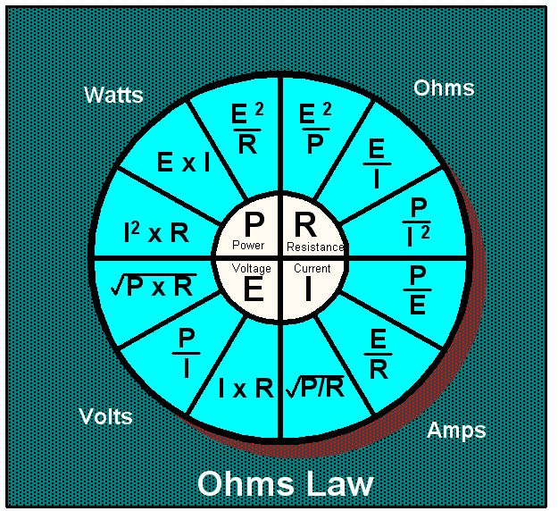
Handy for those learning:

OHMSLAW_zpsygj2ivmm.png~original
 
Okay, update time! sorry I've waited a few days because every time I post a good status, something bad immediately happens :)

It appears installing the 56ohm has done the trick, and I think that combined with removing the insulator on the heat sink. The sink is much mich warmer, so all that heat is now being dissipated there instead of at Rk1, allowing it to run cooler.

The only issue I'm seeing now is that the left side of the amp is underwhelming compared to the right. First I thought it was more gunk in either the volume or balance pot, but I've cleaned them thoroughly and (short of taking them apart) they should be okay. Left side is just low in terms of bass and just a little...meh...compared to the right. A few times at power up there is a slight crackle that works itself out of I crank it good. At loud volumes, left is fine, so I'm thinking it's the transistor pair on the heat sink that's nearing end of life.

Also, I'm picking up a radio station (right side only) in the phono stages, but it's very very very weak and I can live with it.

I triple checked the bias before closing it up, but it could've jumped around in the last few days after being put through some normal use. Anybody seen similar from one side or the other?
 
Back
Top Bottom