Little Bear Tube Phono Pre??

Good point sled. I will see if that makes any difference by running a wire around all the Alu foil and grounding it on the lug.

Vendor seems to think a new board might help so they've sent a new one for me to test. Fingers crossed its a simple fix because up until this point I've not been able to affect the hum at all.
 
Is there any way to get a replacement transformer for this amp? It seems that one of the 200v outputs on my has stopped working and the transformer now has a nice burnt smell to it.


Edit:
I accidentally shorted the output, all seems to be good as of now.
 
New board arrived but it's not really cleaned up the noise. I'm starting to think it's just going to be a consequence of turning up the vol half way, not something I would ever do as it would be silly loud.

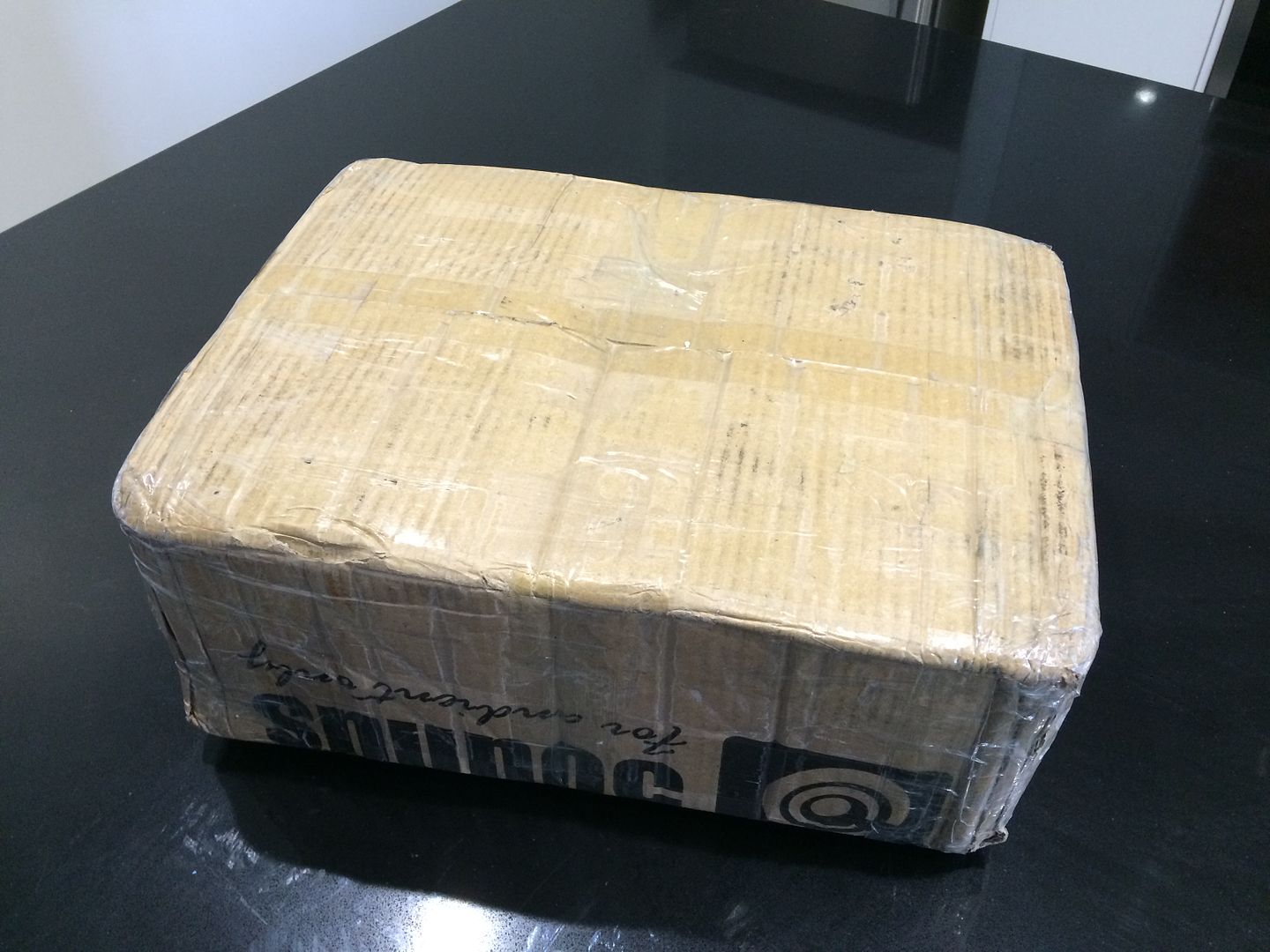
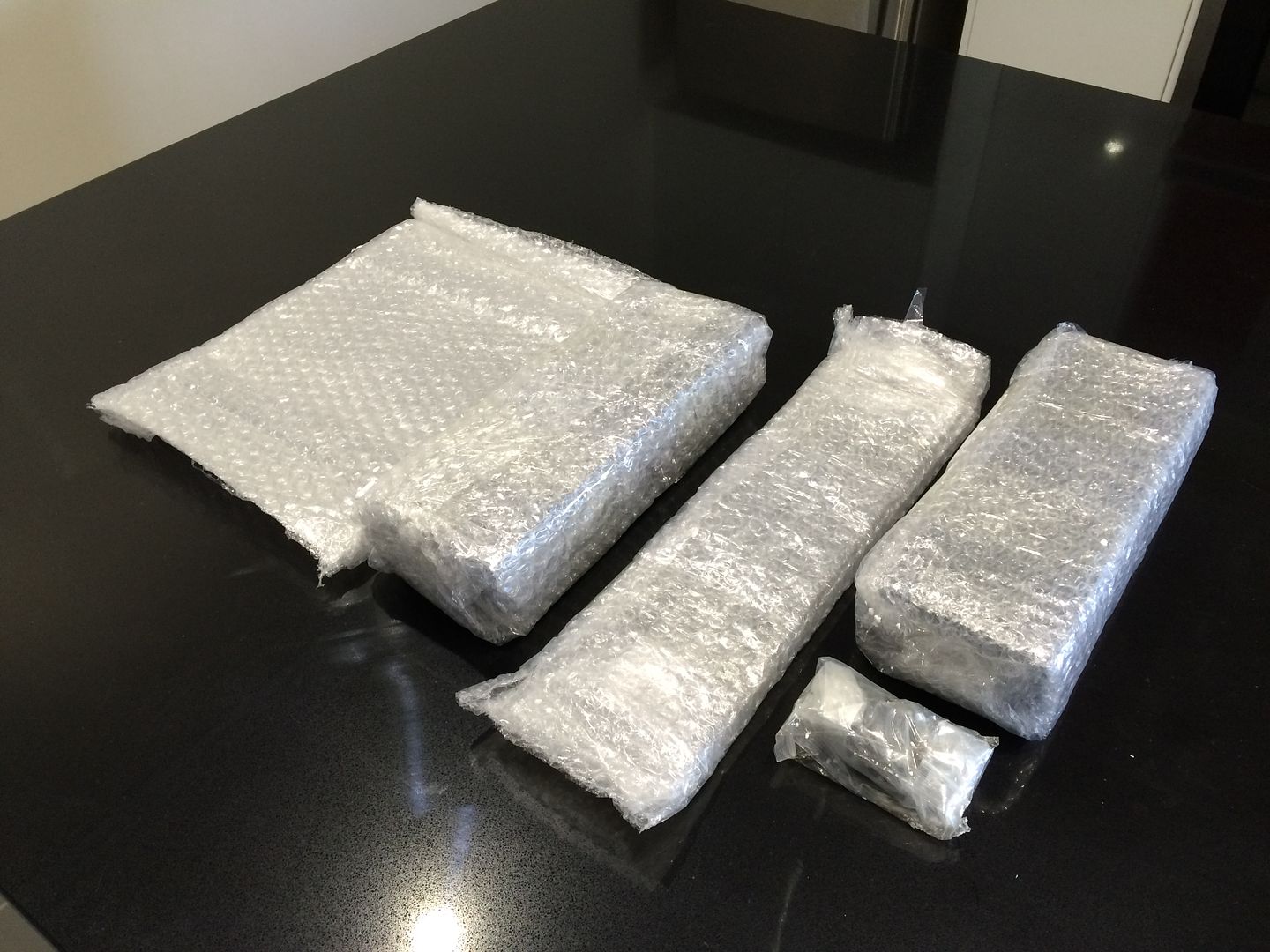
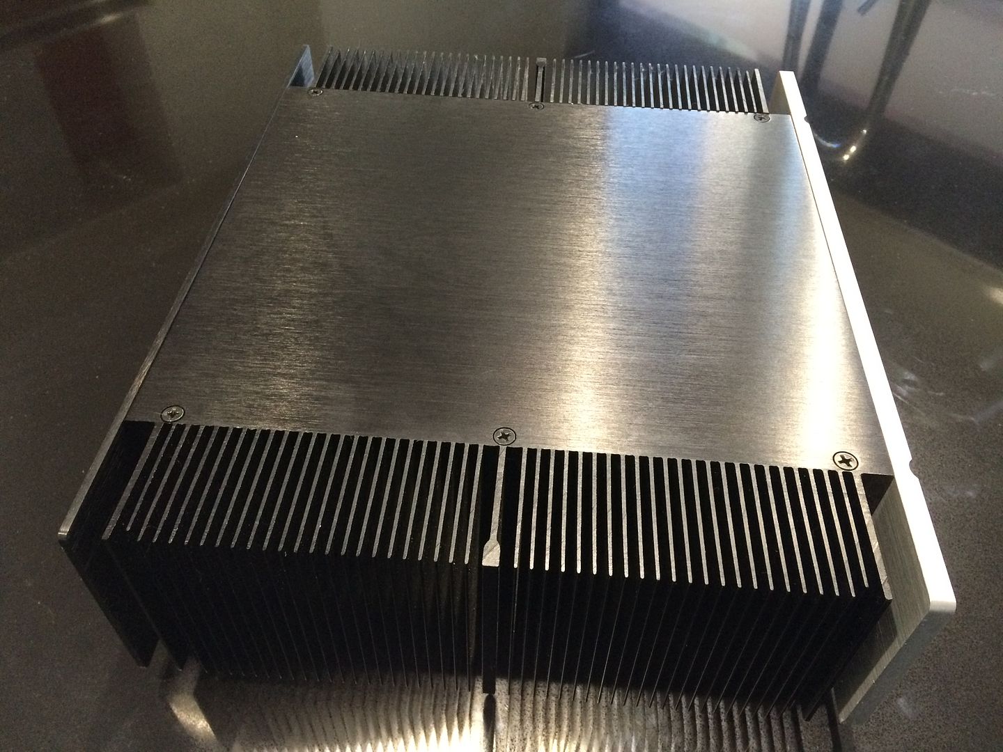
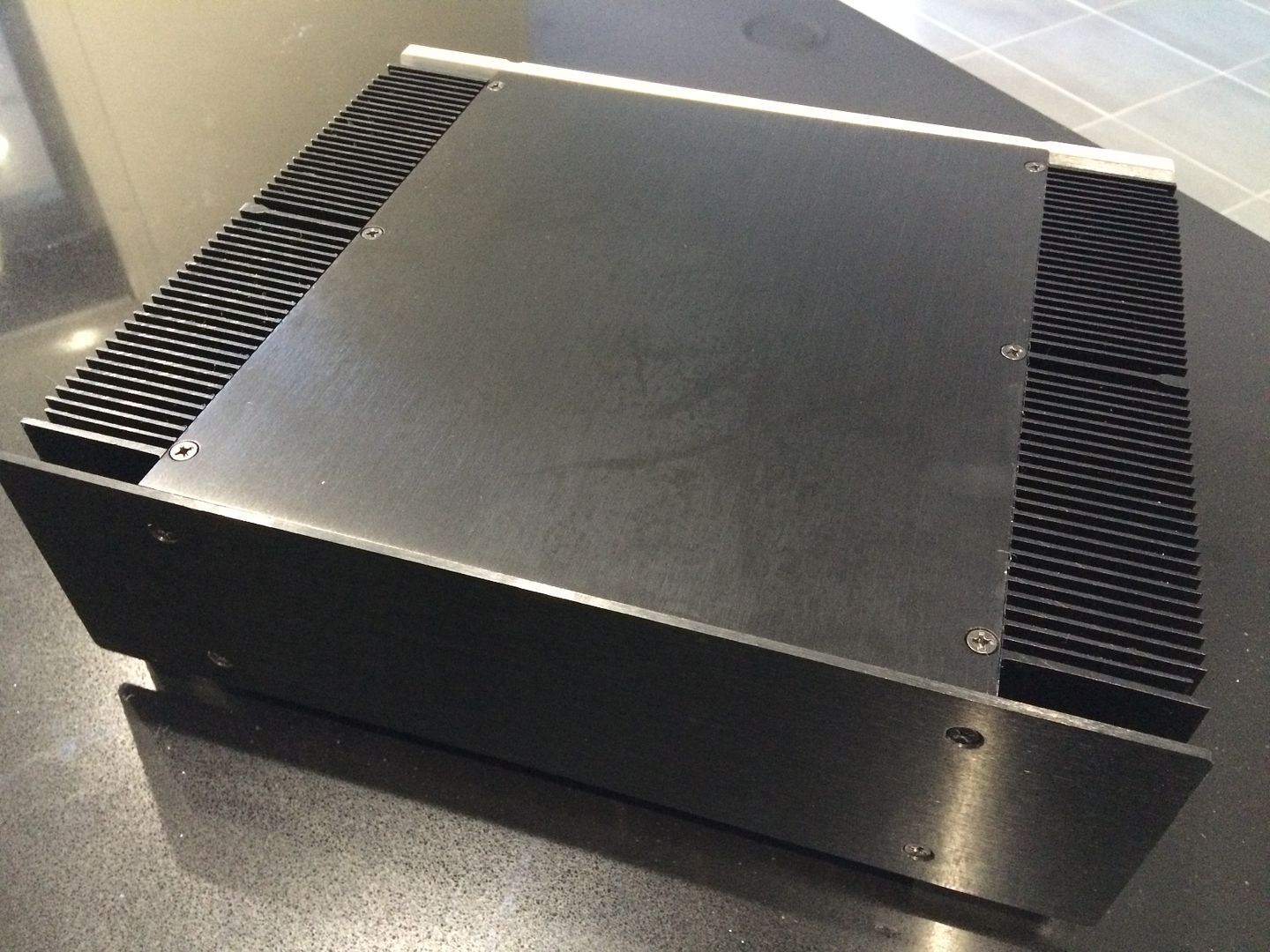
Today I got my latest addition for my LB. I'd been playing with the idea of having a custom case made by a mate with a CNC, however he didn't have the right setup to cut the fins I wanted on the outside.

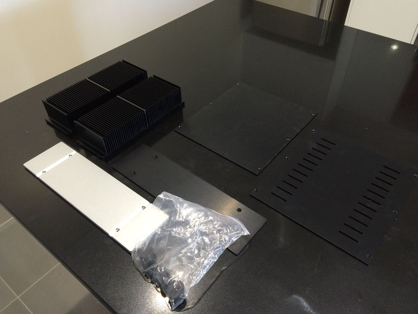
So after a bit of googling I finally found something that was almost identical to what I was designing but with a few nicer touches:


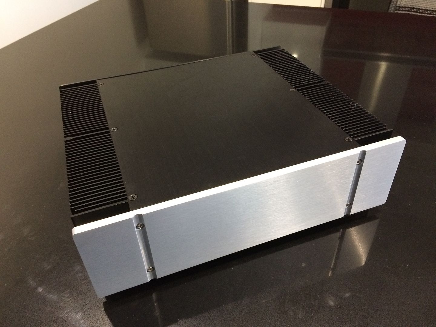
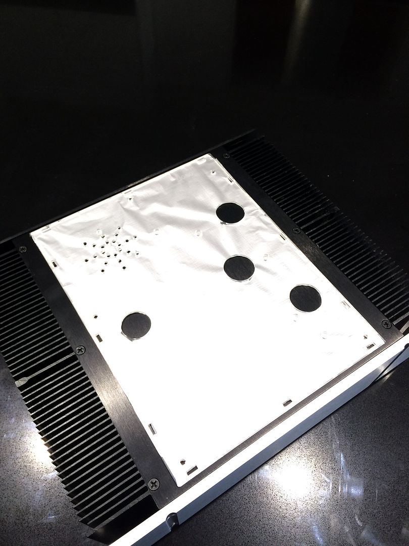
The finned cover is supposed to be the top, but I'm going to use it on the bottom as I'm planning on cutting the top for the tubes and also holes for venting the transformer as per the original Perspex lid.


I've purchased a set of step drills so I can drill out the 20mm approx holes for the tubes, plus I also need to cut the back out for the IEC power connector and also the RCA connectors and earth connector. As you can see the case is perfect dimensions for the LB T10:


I'm planning on re-routing the power and audio cables to the rear of the case so I've purchased some Alu mesh to shield each of them to reduce potential hum. I'm also looking to swap out the power switch for an illuminated LED switch that hopefully will be located on the front of the case.
 
I am still concerned about the mechanical hum the transformer makes, however the vendor seems to think (as did someone else in this thread) that its not the cause of my excessive audio signal path hum.

No, the mechanical hum is not the cause of the audio hum - but the two might be symptoms of the same problem. Transformers are more prone to hum when delivering a lot of current. Power supply ripple is worse when the power supply is delivering a lot of current. Maybe there's a short circuit somewhere (it only needs a solder blob or a stray whisker of wire) which a causing excessive current to be drawn from the power supply. Maybe.
 
New board arrived but it's not really cleaned up the noise. I'm starting to think it's just going to be a consequence of turning up the vol half way, not something I would ever do as it would be silly loud.

Today I got my latest addition for my LB. I'd been playing with the idea of having a custom case made by a mate with a CNC, however he didn't have the right setup to cut the fins I wanted on the outside.

So after a bit of googling I finally found something that was almost identical to what I was designing but with a few nicer touches:


The finned cover is supposed to be the top, but I'm going to use it on the bottom as I'm planning on cutting the top for the tubes and also holes for venting the transformer as per the original Perspex lid.


I've purchased a set of step drills so I can drill out the 20mm approx holes for the tubes, plus I also need to cut the back out for the IEC power connector and also the RCA connectors and earth connector. As you can see the case is perfect dimensions for the LB T10:


I'm planning on re-routing the power and audio cables to the rear of the case so I've purchased some Alu mesh to shield each of them to reduce potential hum. I'm also looking to swap out the power switch for an illuminated LED switch that hopefully will be located on the front of the case.
That's a very nice case and obviously it will involve a lot of work. Given the amount of work, I don't know why you're bothering with the circuit board at all. You might as well make a circuit from scratch using tagstrip and point-to-point wiring and do a better job than the designers of that PCB did in the first place.
 
That's a very nice case and obviously it will involve a lot of work. Given the amount of work, I don't know why you're bothering with the circuit board at all. You might as well make a circuit from scratch using tagstrip and point-to-point wiring and do a better job than the designers of that PCB did in the first place.

Can you point me to a resource? Sounds interesting, although butchering the old PCB sounds much easier.
 
Can you point me to a resource? Sounds interesting, although butchering the old PCB sounds much easier.
Without knowing how much electronics experience you have it's difficult for me to say what's easy and what's difficult but wiring a few components onto tag strips and valve bases isn't very difficult in my opinion. What usually puts people off is the hassle involved in the casework but it looks like you can tackle that.
But what about a circuit? I did think that a quick google search would throw up plenty of designs that I liked the looks of, but no - I found a lot of circuits that I didn't like the looks of at all!
This is the well-known circuit which was published by RCA in their application notes:
https://www.hndme.com/storeschematics7.html
However, it does have a high output impedance and ideally it needs to be fed into a high impedance line pre-amp. Using it straight into modern solid-state gear with a low(ish) input impedance might cause problems. An improvement for the circuit would be to add a buffer at the output. The second circuit on this page ...
http://www.valvewizard.co.uk/accf.html
(with 470k, 1k, 470R, 8k resistors) should work fine with the component values shown.

BTW, in my opinion power supplies should be in ugly boxes. Why? Because ugly boxes get put on the floor behind the rack and their even uglier magnetic fields are kept away from sensitive audio circuits. Beautiful power supplies get put next to beautiful amplifiers and can cause problems. Putting the power supply in the same box as the audio circuit can work out fine but bear in mind that phono pre-amps have a lot of gain at low frequencies (20dB more than the midrange) and transformers can cause serious hum. Be prepared to experiment and find the best layout before committing your self by drilling lots of holes etc.
 
Very interesting reading there. Thanks. I think I need to read up a bit more before jumping in to a project, so for this case I'm going to adapt it for the T10, however you have piqued my interest and I'm now going to read up on building my own stuff.

Would like to build my own Preamp and Monoblocks one day, so I'll start the learning now.
 
Listening to some wax tonight without my T10 makes me realise how much it makes the audio sparkle. Thing is getting some upgrades so looking forward to getting it back in the system.
 
Listening to some wax tonight without my T10 makes me realise how much it makes the audio sparkle. Thing is getting some upgrades so looking forward to getting it back in the system.
Depends what you're comparing it to I guess. So many people tearing them apart so must be plenty of room for improvement.
 
Sure, I doubt they're perfect but I'm noticing a distinct reduction in bass, clarity and space when I'm running my PL-518 straight in to my KA-7100.

Shows how dangerous this hobby is as there are so many benefits to be had as you progress up the chain.
 
Sure, I doubt they're perfect but I'm noticing a distinct reduction in bass, clarity and space when I'm running my PL-518 straight in to my KA-7100.
Shows how dangerous this hobby is as there are so many benefits to be had as you progress up the chain.
Haha, yeah , I learned a long time ago that everything sounds fine until you listen to gear a level up.
 
I learnt that with motorbike suspension. Rode a new bike with great forks and then spent the next 2 years pulling mine apart trying to chase that feeling.

Most of the time; "ignorance is bliss!"
 
Well I'm the bloke in Melbourne. Yes I did make a custome Mimic for you. Glad you like it at least that is how I read your comment above. For the price they are probably unbeatable.

A guy in Tassy (also an SNA member) has both a Mimic and my tube MM phone pre; La Gitana. He likes both for different reasons. I got back the first Mimic I ever built called The Heran after Bruce Heran of oddwatt fame in America who developed the cct. It spent the last year or so in Washington. The guy who bought it sold his second TT so I swapped it out for one of my DC blockers (DC Duffer). Another SNA member has just bought The Heran off me.

http://retro-thermionic.blogspot.com.au/2013/11/opamp-phono-preamp-with-high-riaa-eq.html
 
I spent about an hour flicking through your blog posts last night. Very interesting read and some amazing products you out together!
 
Well I'm the bloke in Melbourne. Yes I did make a custome Mimic for you. Glad you like it at least that is how I read your comment above. For the price they are probably unbeatable.

A guy in Tassy (also an SNA member) has both a Mimic and my tube MM phone pre; La Gitana. He likes both for different reasons. I got back the first Mimic I ever built called The Heran after Bruce Heran of oddwatt fame in America who developed the cct. It spent the last year or so in Washington. The guy who bought it sold his second TT so I swapped it out for one of my DC blockers (DC Duffer). Another SNA member has just bought The Heran off me.

http://retro-thermionic.blogspot.com.au/2013/11/opamp-phono-preamp-with-high-riaa-eq.html
Not *totally* Off Topic ;)
Little Bear is very budget entry level. I am not surprised he likes the Mimic and a decent tube set for different reasons. Running MCs runs me into trouble with SUTs with MM Tubes.
The MC circuit on the Mimic you did for me is outstanding and better than trying to use the MC>SUT (Ortofon T-5) > MM circuit. Still puting an hour on it here and there and wouldn't mind if it 'smoothed' the topend a bit more. Other buyer said he thought it got better all the way through the first battery set but it uses so little I don't think I've seen the voltage change yet !
 
Hi,
I am new in the discussions about the LB, although I read the threads completely and could get a lot of hints, how to improve or modify this tube-amp.
I bougt my little bear in 2013 and the mods were as usual: hum reduction, grounding, tube shielding and russian tubes 6n2 and an other rectifier tube from russian sources.
In this respect the little bear is a bargain for what you get as music-fun factor. But I wanted to go further and so I invested in better capacitors. First I installed the green russian Oil-paper capacitors with 0.47µF like these ones after the second and the third tube
http://www.ebay.de/itm/Olpapier-MP-...346906?hash=item3f5ca65f5a:g:jrsAAOSwHjNV~p5C
and then Jantzen superior Z-Cap 0,1µF after the first tube as you can see here
http://www.ebay.de/itm/1-pc-Jantzen...984085?hash=item4d4826cc95:g:jCUAAOSwo6lWPerc
This brings more musical life to the LB and in combination with the exchange of the resistors with Vishay Dale CMF-55 variants, the LB plays in a positively manner very straight ahead and brings much fun while listening.
But I tried some other things that aren't described so far and are maybe interesting for some other users. So I first bring the schematic on the table once more:
upload_2016-10-15_19-21-26.jpeg
Some people changed the 62k resistors with 47k as usual for MM-Systems. I tried this too, but found that 50.1k Dale resistors give more pleasure with my Audio Technica AT155LC System.
I then changed the output resistor R25 to see, what happens to the sound. With an 2k output resistor the sound gets more three-dimensional and fits best to to my listening room. Meanwhile I removed the electrolytic capacitor at the cathode on tube 2 because it causes some harshness and distortion.
The last and actual modification concerns the resistor R1 on the cathode side of the cathode follower (tube 3). I changed it to 17k and were very surprised, that this modification brings the LB to a very calm and soft mood, that makes the music so wonderful.
I'm not an electrician and my experience in tube amping is in the beginner status. So I can't tell you what happens in the third tube or why the sound is now so „smooth“. But I would be very interested if other people would recognize the same improvement with this mod.
I made recordings of some LPs and the results are very promising and show no irregular effects.
The next picture shows my modifications on the schematic in summery:
upload_2016-10-15_19-21-18.png

with kind analogue greetings from Germany
Michael
 
Last edited:
I then changed the output resistor R25 to see, what happens to the sound. With an 2k output resistor the sound gets more three-dimensional and fits best to to my listening room. Meanwhile I removed the electrolytic capacitor at the cathode on tube 2 because it causes some harshness and distortion.
The last and actual modification concerns the resistor R1 on the cathode side of the cathode follower (tube 3). I changed it to 17k and were very surprised, that this modification brings the LB to a very calm and soft mood, that makes the music so wonderful.
Removing the capacitor at the cathode of the second valve will reduce the open loop gain and raise the output impedance of the second stage. Since the RIAA eq is in the feedback loop I wouldn't want to reduce the open loop gain.

The grid of the third valve is at a high voltage and the cathode resistor is setting the bias current and operating point. Changing from 62k to 17k is a huge change and will cause the valve to draw a lot more current. Did you measure anything?
 
Did you measure anything?

No, I haven't measered currents or voltages but I checked frequency spectrum with corresponding and comparable CD albums and with older recordings made before this modification. So this is no real measurement at all but only my personal impression of an improvement.

Here you can see such an frequency spectrum from the LP/CD Vangelis, Soil festivities from 1983 (a 90s section):

upload_2016-10-16_20-43-35.png
http://www.imagenetz.de/f85ccd749/Frequenzvergleich-CD-LP-20Hz-16kHz.png.html
 
Last edited:
Back
Top Bottom