

deltalight
AK Subscriber
Marantz 2285B - New Output Cap Assy
I recently restored the popular Marantz 2285B and decided to design a new modular output cap assy. Two current methods are the “Gut and Stuff” method and what I will call the “Capacitor Platform” method. “Gut-and-Stuff” uses the following steps:
1) Remove old cap from unit
2) Remove the bottom of can
3) Gut the old cap assy out and clean the inside can
4) Solder cap leads to old terminal plate.
5) Stuff new caps into the existing can.
6) Re-attach/re-seal endcap onto can
7) Re-mount the rebuilt cap back into unit.
Steps for the Capacitor Platform method:
1) Fabricate a platform i.e. resin-filled cup, capacitor clamp, etc. that holds snap-in caps
2) Clamp or insert snap-in caps into the new clamp or molded platform
3) Interface the new assy into the Power Supply section of the unit
Both “Gut-and-Stuff” and the Capacitor Platform methods have been discussed here:
2285B recap & binder post conversion
http://audiokarma.org/forums/index.php?threads/2285b-recap-binder-post-conversion.420274/
Scary repair - 2285B dual-section caps failed
http://www.audiokarma.org/forums/in...repair-2285b-dual-section-caps-failed.281050/
The current methods work fine, but I wanted a different output cap solution for the 2285B. When I couldn’t find the solution I was looking for, I designed one using what I call the "Modular" method which incorporates a PC board. Using lessons learned from previously designed Output Cap assys, I wanted the following design features:
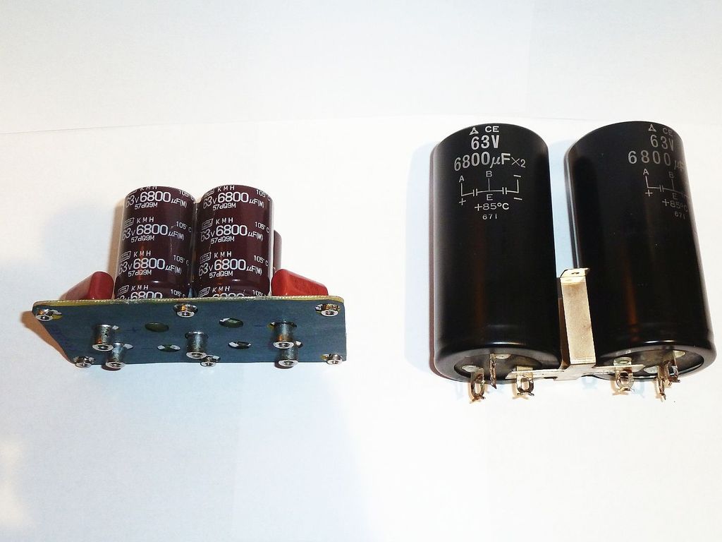
1) Keep assembled module within the chassis constraints of the original two 6800uF 63v Dual caps
2) Use 30mm snap-in caps which allows for a larger selection of values
3) Incorporate screw terminals in the same location as the original solder lugs for ease of service
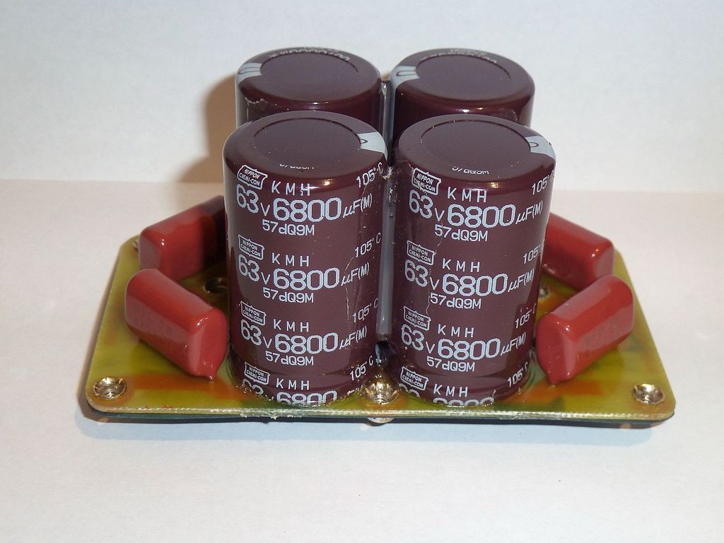
4) Bypass the 6800uF 63v electrolytic caps with 4.7uF PP film parts for enhanced frequency response
5) Use star-ground techniques for solid electro-mechanical mounting eliminating the original ground strap
There are six threaded standoffs on the outer edge of the assy. Six holes are drilled into the chassis for the 6-32 screws that secure the assy to the chassis. Each nickel-plated standoff is electrically connected to the center ground terminal. This provides excellent electrical grounding and replaces the original ground strap. The new assy is mounted very solid.
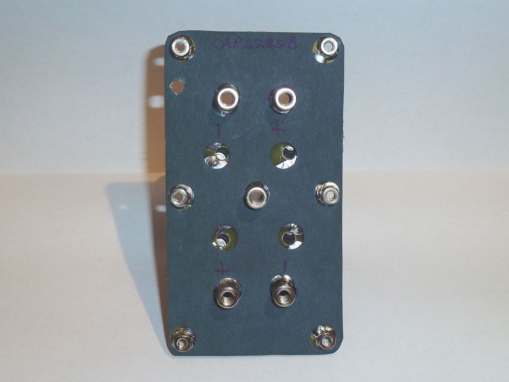
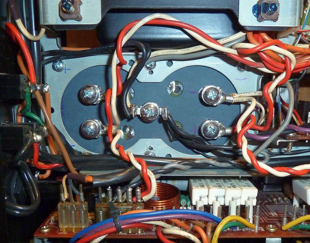
The new modular assy sits 1/8-in off the top chassis where the obsolete Dual Caps were mounted to accommodate electrical isolation on the PC board traces. To prevent any possible electrical shorting, a piece of fish paper was cut, punched and secured with adhesive on the assy bottom to accommodate the six standoffs and five output terminals [see photo]
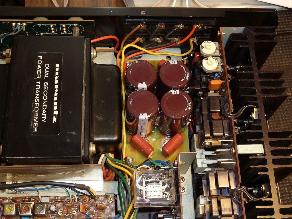
As shown in the photo, the edges of the assy fit right up to the vertical edges of the chassis which still left room for output speaker wires next to the transformer on one side and space for ventilation on the other side. The four 4.7uF polypropylene bypass caps fit perfectly on the PC board.
The new assy has permanently-mounted nickel-plated terminals which are threaded for 10-32x3/8 Philips screws. PC board to chassis clearance came out perfect. Fits perfect. Success!
Summary
The new Marantz 2285B retrofit Output Cap assy fits and performs great. The only issues are 1) the new modular assy does not retain the identical look of the original Dual Caps 2) more parts are used making the assy cost higher. The “Gut-and-Stuff” method requires about the same amount of assy time, but uses fewer components, has lower cost and retains the original internal look. The Capacitor Platform method probably costs less even using capacitor clamps.
Comments?
I recently restored the popular Marantz 2285B and decided to design a new modular output cap assy. Two current methods are the “Gut and Stuff” method and what I will call the “Capacitor Platform” method. “Gut-and-Stuff” uses the following steps:
1) Remove old cap from unit
2) Remove the bottom of can
3) Gut the old cap assy out and clean the inside can
4) Solder cap leads to old terminal plate.
5) Stuff new caps into the existing can.
6) Re-attach/re-seal endcap onto can
7) Re-mount the rebuilt cap back into unit.
Steps for the Capacitor Platform method:
1) Fabricate a platform i.e. resin-filled cup, capacitor clamp, etc. that holds snap-in caps
2) Clamp or insert snap-in caps into the new clamp or molded platform
3) Interface the new assy into the Power Supply section of the unit
Both “Gut-and-Stuff” and the Capacitor Platform methods have been discussed here:
2285B recap & binder post conversion
http://audiokarma.org/forums/index.php?threads/2285b-recap-binder-post-conversion.420274/
Scary repair - 2285B dual-section caps failed
http://www.audiokarma.org/forums/in...repair-2285b-dual-section-caps-failed.281050/


The current methods work fine, but I wanted a different output cap solution for the 2285B. When I couldn’t find the solution I was looking for, I designed one using what I call the "Modular" method which incorporates a PC board. Using lessons learned from previously designed Output Cap assys, I wanted the following design features:
1) Keep assembled module within the chassis constraints of the original two 6800uF 63v Dual caps
2) Use 30mm snap-in caps which allows for a larger selection of values
3) Incorporate screw terminals in the same location as the original solder lugs for ease of service
4) Bypass the 6800uF 63v electrolytic caps with 4.7uF PP film parts for enhanced frequency response
5) Use star-ground techniques for solid electro-mechanical mounting eliminating the original ground strap
There are six threaded standoffs on the outer edge of the assy. Six holes are drilled into the chassis for the 6-32 screws that secure the assy to the chassis. Each nickel-plated standoff is electrically connected to the center ground terminal. This provides excellent electrical grounding and replaces the original ground strap. The new assy is mounted very solid.

The new modular assy sits 1/8-in off the top chassis where the obsolete Dual Caps were mounted to accommodate electrical isolation on the PC board traces. To prevent any possible electrical shorting, a piece of fish paper was cut, punched and secured with adhesive on the assy bottom to accommodate the six standoffs and five output terminals [see photo]

As shown in the photo, the edges of the assy fit right up to the vertical edges of the chassis which still left room for output speaker wires next to the transformer on one side and space for ventilation on the other side. The four 4.7uF polypropylene bypass caps fit perfectly on the PC board.

The new assy has permanently-mounted nickel-plated terminals which are threaded for 10-32x3/8 Philips screws. PC board to chassis clearance came out perfect. Fits perfect. Success!
Summary
The new Marantz 2285B retrofit Output Cap assy fits and performs great. The only issues are 1) the new modular assy does not retain the identical look of the original Dual Caps 2) more parts are used making the assy cost higher. The “Gut-and-Stuff” method requires about the same amount of assy time, but uses fewer components, has lower cost and retains the original internal look. The Capacitor Platform method probably costs less even using capacitor clamps.
Comments?
Last edited: