

duncan
flâneur in training
This old friend has been relegated to a drawer since the acquisition of a Bryston DAC for my main (okay, only) system, and I decided to tweak on it a bit.
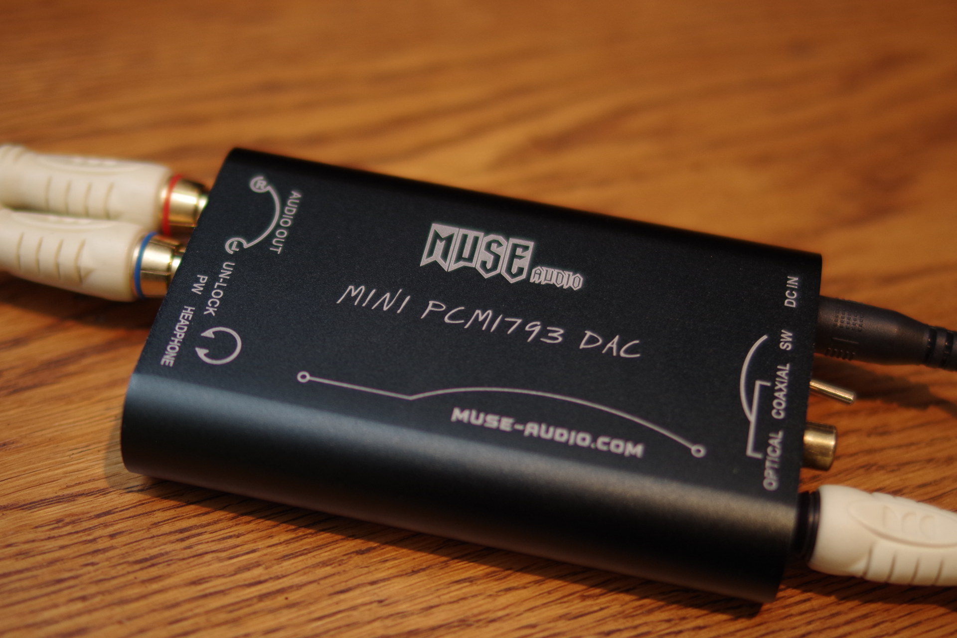
I included a couple of LME49720 op-amps in my last Mouser order with this DAC in mind.
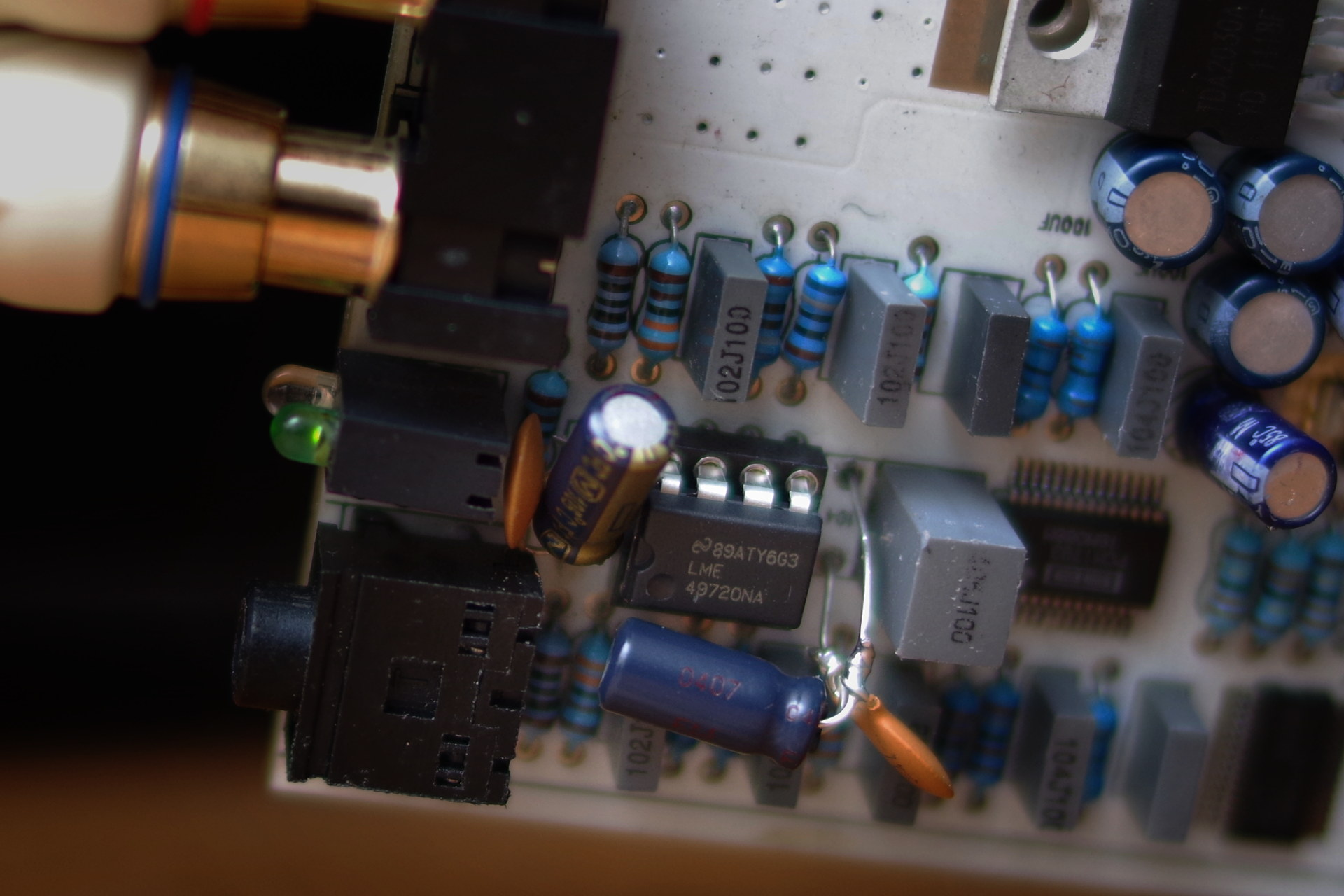
Today's lesson: how hard it is to work on these little boards. Everything is in there pretty tight, the component holes are barely big enough to get the leads through, and the lead-free solder just doesn't want to let go. I used a combination of a plunger-type sucker and Chemwick to get it as clean as I could, but nothing would come loose; next I added some leaded solder to mix with what was there, desoldered that, and got a couple of pins free. By then I started to worry about damaging the board. Finally I removed the original output op-amp (which was an OP275, though the board was labeled OPA2134) by force, breaking the body away from its pins so they could be removed one at a time, which was much easier; then reamed out all the holes a little with a dental pick and installed a DIP-8 socket. Checking continuity from each pin to its neighboring components, I found one pad disconnected, and added a little jumper on the bottom of the board to fix it. So far so good, kinda.
The original circuit includes rectangular 0.1uf caps from pins 8 and 4 (the power supply rails) to ground. I removed these also - they were not quite as difficult, but still took some patience. I wanted those out so I could replace them with pairs of 2.2uf electrolitics with 0.1uf ceramics in parallel, which is pretty close to TI's recommendation on the data sheet:
The LME49720 requires adequate power supply decoupling to ensure a low total harmonic distortion (THD). Place a low equivalent-series-resistance (ESR) ceramic capacitor, typically 0.1 μF, within 2 mm of the V+ and V- pins. This choice of capacitor and placement helps with higher frequency transients, spikes, or digital hash on the line. In addition to the 0.1 μF ceramic capacitor, it is recommended to place a 2.2 μF to 10 μF capacitor on the V+ and V- pins. This larger capacitor acts as a charge reservoir, providing energy faster than the board supply, thus helping to prevent any droop in the supply voltage.
The wording there is a little ambiguous, and they probably mean to put the larger cap between pins 4 and 8, but I thought it had to be at least as good to give each its own 2.2uf reservoir parallel to the existing cap. In this board though it's hard to add anything at all because space is so tight. Pin 8's cap pair wasn't much of a problem, but pin 4's had an obstacle, a larger cap nearby, and I had to leave longer leads than I would have liked so that it was possible to bend the caps around to the side and still fit in the little cigarette-pack sized case.
In the end, not the prettiest workmanship ever ...
Got it all back together and plugged it in; no smoke. I've run a couple of classical and jazz redbook CDs through it and am pleased so far with the sound. Now it's playing the Rachmaninov 3rd symphony (Vladimir Ashkenazy cond. Concertgebouw Orchestra, London 455-798-2, fantastic recording). I don't have a way to A/B against the unmodified box, but subjectively it's an improvement in warmth and in the sweetness of the strings. Dynamics seem more subtle. The full orchestra entrance after the quiet introduction to the first movement gives a nice frisson I wasn't getting before the change.
It would be a lot to ask of it to compete with the Bryston BDA-1, and it doesn't, particularly in imaging/soundstaging, but despite my clumsiness it's a satisfying update for very little money.
Does anyone have thoughts on the placement of the added electrolytic(s)?
I included a couple of LME49720 op-amps in my last Mouser order with this DAC in mind.
Today's lesson: how hard it is to work on these little boards. Everything is in there pretty tight, the component holes are barely big enough to get the leads through, and the lead-free solder just doesn't want to let go. I used a combination of a plunger-type sucker and Chemwick to get it as clean as I could, but nothing would come loose; next I added some leaded solder to mix with what was there, desoldered that, and got a couple of pins free. By then I started to worry about damaging the board. Finally I removed the original output op-amp (which was an OP275, though the board was labeled OPA2134) by force, breaking the body away from its pins so they could be removed one at a time, which was much easier; then reamed out all the holes a little with a dental pick and installed a DIP-8 socket. Checking continuity from each pin to its neighboring components, I found one pad disconnected, and added a little jumper on the bottom of the board to fix it. So far so good, kinda.
The original circuit includes rectangular 0.1uf caps from pins 8 and 4 (the power supply rails) to ground. I removed these also - they were not quite as difficult, but still took some patience. I wanted those out so I could replace them with pairs of 2.2uf electrolitics with 0.1uf ceramics in parallel, which is pretty close to TI's recommendation on the data sheet:
The LME49720 requires adequate power supply decoupling to ensure a low total harmonic distortion (THD). Place a low equivalent-series-resistance (ESR) ceramic capacitor, typically 0.1 μF, within 2 mm of the V+ and V- pins. This choice of capacitor and placement helps with higher frequency transients, spikes, or digital hash on the line. In addition to the 0.1 μF ceramic capacitor, it is recommended to place a 2.2 μF to 10 μF capacitor on the V+ and V- pins. This larger capacitor acts as a charge reservoir, providing energy faster than the board supply, thus helping to prevent any droop in the supply voltage.
The wording there is a little ambiguous, and they probably mean to put the larger cap between pins 4 and 8, but I thought it had to be at least as good to give each its own 2.2uf reservoir parallel to the existing cap. In this board though it's hard to add anything at all because space is so tight. Pin 8's cap pair wasn't much of a problem, but pin 4's had an obstacle, a larger cap nearby, and I had to leave longer leads than I would have liked so that it was possible to bend the caps around to the side and still fit in the little cigarette-pack sized case.
In the end, not the prettiest workmanship ever ...
Got it all back together and plugged it in; no smoke. I've run a couple of classical and jazz redbook CDs through it and am pleased so far with the sound. Now it's playing the Rachmaninov 3rd symphony (Vladimir Ashkenazy cond. Concertgebouw Orchestra, London 455-798-2, fantastic recording). I don't have a way to A/B against the unmodified box, but subjectively it's an improvement in warmth and in the sweetness of the strings. Dynamics seem more subtle. The full orchestra entrance after the quiet introduction to the first movement gives a nice frisson I wasn't getting before the change.
It would be a lot to ask of it to compete with the Bryston BDA-1, and it doesn't, particularly in imaging/soundstaging, but despite my clumsiness it's a satisfying update for very little money.
Does anyone have thoughts on the placement of the added electrolytic(s)?
Last edited: