MX-1000 Sub Circuit Board Changes

sonavor

Active Member
I have had the opportunity to come across more than one MX-1000 power amplifier in the last couple of years. Some are MX-1000 and some MX-1000U units.
I have an original copy of the service manual and a photo copy. They are the same manual though. My question regards some circuitry differences in the left and right sub circuit boards (sub ckt boards 1 & 2). Those are the power boards containing H.C.A., I-Amp and A.P.S. The pictures of the sub circuit board traces match a couple of my MX-1000 amps but some technician had modified part of the circuitry. Other MX-1000 units I have obtained appear to have an updated sub circuit PCB so that "mod" must have been a retrofit to update original boards to the new one.

Is there an updated service manual that shows this?

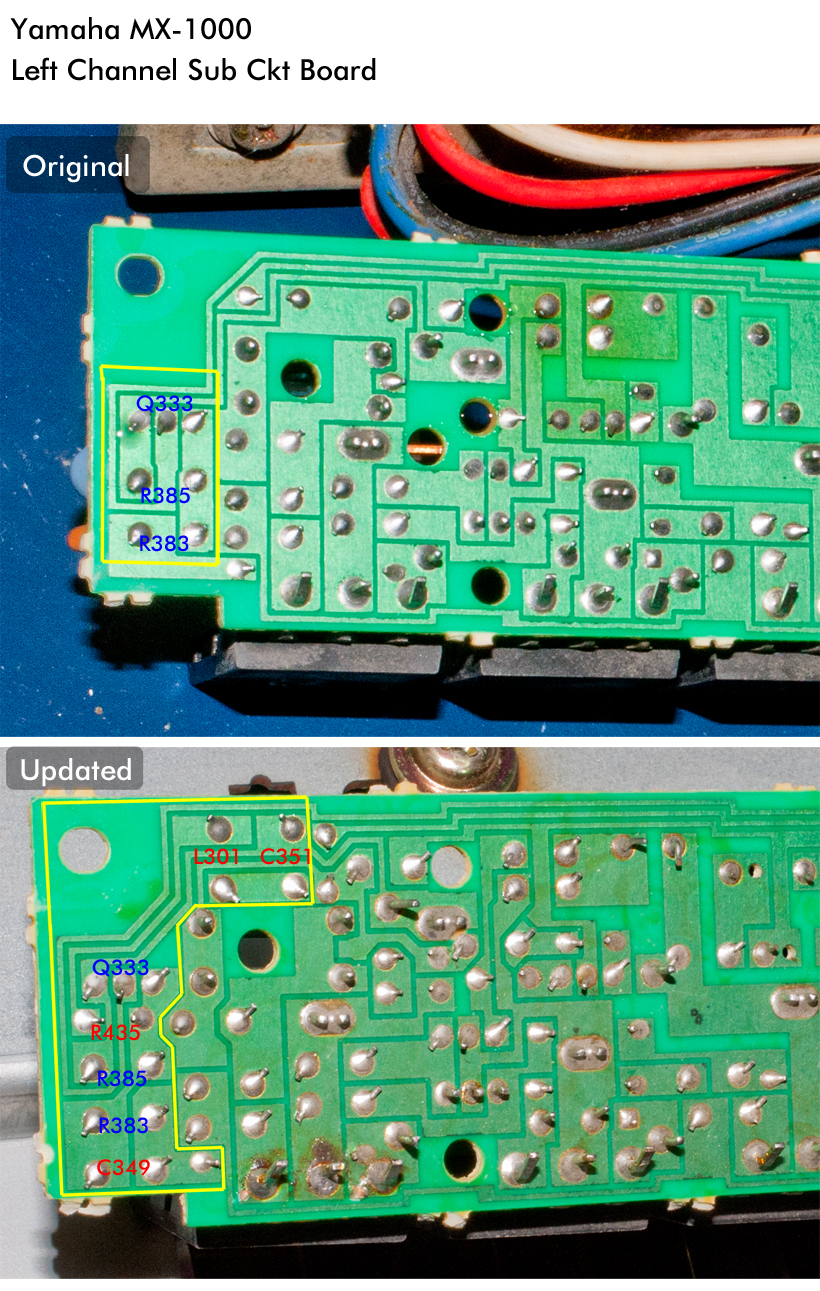
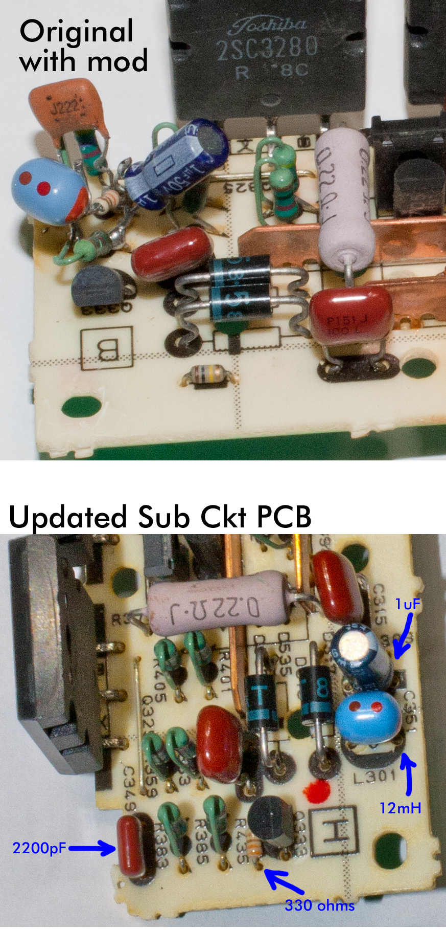
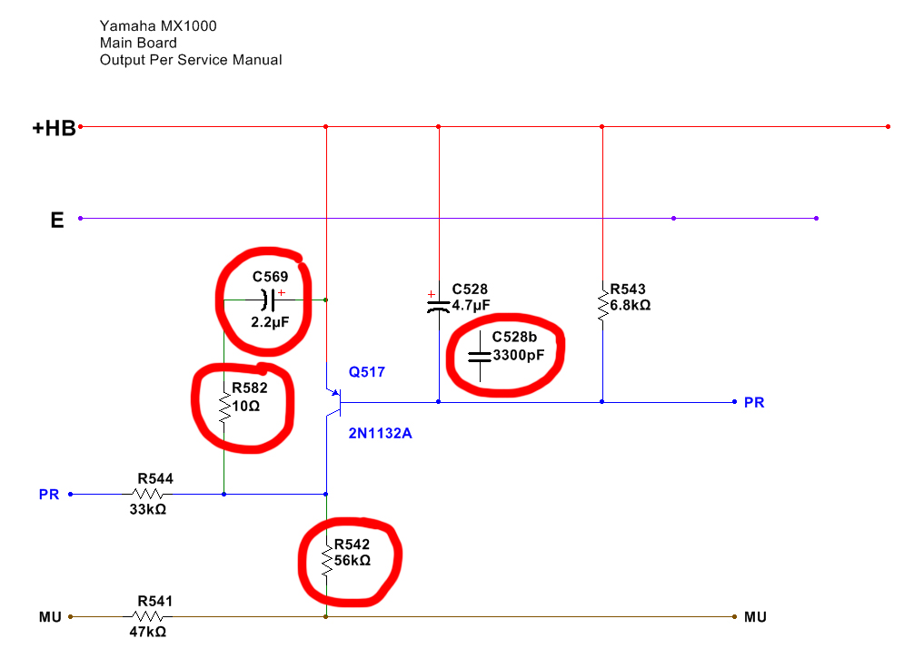
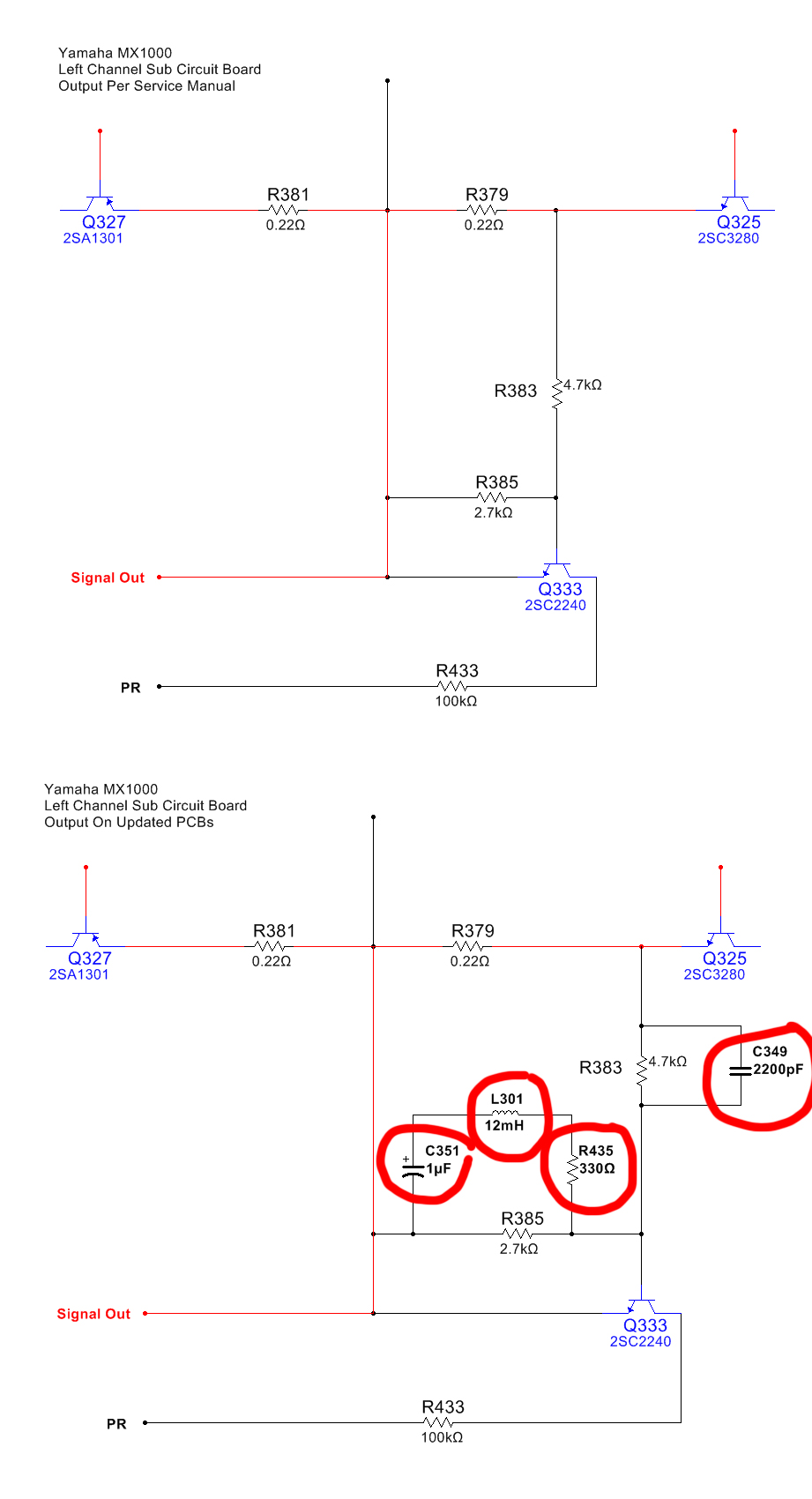
Here is what I am talking about. In this picture, the top part is the part of the sub circuit board schematic that has was updated. The update is shown in the bottom part of the picture. Four components were added: C351, L301, R435 and C349.

mx1000_sub_ckt_pcb_difference.jpg
 
Last edited:
Here is a picture of the trace side on two of the MX-1000 left channel sub circuit boards. The top one is the original board that matches the service manual. The bottom one is the updated board.

MX-1000_LCH_sub_ckt_pcb_diff.jpg
 
Here is a picture of the component side of the two versions of the left channel sub circuit board. The top picture shows the original board with the modification that added the four additional components. The bottom picture shows the updated version of the board with the four components in designated locations.

MX-1000_LCH_sub_ckt_pcb_diff_02.jpg
 
Another question I have (besides if there is an available update to the service manual), is can anyone explain the function of the added four components to the protection circuit detection? Were they added to make it more stable?
 
I am also curious to find the answer to this question

Hello Sonavor,

I wish I would now the answer to your question. I am too much of a newbie when it comes to electronic circuits.
I also have an MX-1000 that I purchased in a very bad shape. I will be working on it at some point and trying to restore it.

The schematic I have is in PDF format and does not show the mod.
The boards of my amp also do not have the mod...and that could be one of the reasons why some of the transistors are literally blown to pieces..LOL

I will be very interested in your findings.
 
The board with the post-production mod is marked with an "B" and came out of an MX-1000U unit. The board with the mod designed into the board is marked with a "H" and is out of an MX-1000.

I have a main board along with the left and right sub circuit boards that has burned component damage. It's hard to say how these damaged units got that way. Components could have failed, maybe something like a lightning strike or it could be someone's failed attempt at a repair.

I found another mod to the main board of the MX-1000U that brings it up to the main board of the MX-1000 units. I'm checking those against the service manual schematics and will post pictures of the differences. I suspect it will be the same as the sub circuit boards 1 & 2 where the mod is not documented in my service manual.
 
Here is an MX-1000U main board. The board is identified with NA09 XE223 - 766. The number 960 is blacked out. There appears to be a revision "C" marked on the board as well.

The picture below shows additional components (C528, C569, R542 and R582) added to the board which make that part of the circuit match the MX-1000 NA09 XE223-960 board.

MX-1000U_main_board_with_mod_01.jpg
 
Here is a picture of an MX-1000 NA09 XE223 - 960 main board. The revision is "F" and it has the 766 blacked out in favor of 960. This board has the C528, C569, R542 and R582 components mounted it designated spots on the board.

Note that this particular MX-1000 board has a number of burned components. The white glue on the electrolytic capacitors is visible. I haven't seen signs of the white glue corroding things like the brownish glue on the Yamaha M-70 amps.

MX-1000_main_board_960_01.jpg
 
Here is what I believe the circuit modification is between the MX-1000U 766 board and the MX-1000 960 board. Components C569, R582 and R542 were added. C528 was replaced. The two MX-1000U boards that I have seen have this mod soldered on the trace side of the main board. One of the MX-1000U main boards have the C528 capacitor as the 4.7uF electrolytic shown in the service manual while the other one has that replaced by a 2700pF non-electrolytic capacitor. The MX-1000 units have the 3300pF non-electrolytic capacitor.

Yamaha-MX-1000-Main-Board-Schematic_01.jpg
 
Woow so it looks like Yamaha initially sold a not so fully tested product. I will post some photos with the damage to the amp I have. It is pretty graphic in electronics terms.
My amp also has extensive corrosion to the chassis which could have accrued post "destruction" but could have been also one of the reasons for it, besides the "immature" design.
The model I have is a 1000U and from what I begin to uncover, has none of the mods you are describing.
Any findings you share will be really appreciated and put to good use when I start the resurrection process of my amp.
I am sure that one of the more knowledgeable members of this forum could enlighten us with additional knowledge.
I would also consider posting this issue on the DIY Audio forum. There, I found a nice discussion about Yamaha's amp design which included this model, albeit, nothing in reference to the protection circuit, but rather to the adjusting bias.
 
From what I understand, the MX-1000U is for the US market and the only difference comparing to the MX-1000, should be the AC supply voltage set to 120v.
 
K, my MX-1000 board is version 766.
So you are saying that with this last mode, the difference is also consistent to the "U" vs the non "U" models?
If so, then it may be strictly related to the voltage supply being fixed vs adjustable...I am mostly guessing here...
 
K, my MX-1000 board is version 766.
So you are saying that with this last mode, the difference is also consistent to the "U" vs the non "U" models?
If so, then it may be strictly related to the voltage supply being fixed vs adjustable...I am mostly guessing here...

No, what it looks like to me is that Yamaha made a few versions of MX-1000 as listed in the service manual. The "/U" version was US only I believe. The "R" version is listed as general and is just called MX-1000. So the boards have a number for the version they are for. On the main board there is the 766 for the MX-1000/U version and a 960 for the MX-1000 (R).

Then there is a board revision letter. I have shown in my pictures early letter revisions with the post-production mods on them while the later revisions of the boards have the new components designed in. I just haven't found a Yamaha schematic or service manual update for the later revisions of those boards.

That was my original question on this posting - whether anyone has any information about the modifications Yamaha made.

The modifications I have posted appear to be related to the protection circuitry but I don't think I would take that to mean Yamaha didn't properly test their amps. I think the mods are probably just a result of normal evolution of a design. I have some boards from the later revisions that got smoked by someone so even those amps got mistreated.
 
K, that makes sense and makes me feel a little better.
The updated schematic, do you mind sharing it? Do you know it the schematic available on the AK database is the updated version?
 
The only update to the schematic is what I have drawn in myself. All of the published versions I have found so far are for the earlier revisions of the boards.
 
Thank you! I have already made note of your diagrams.
Do you think would be a good idea to also post your questio on the DIY audio forum? I am new to this forum (as well as to the DIY forum) so I am not sure of any conflict of interest.
 
It's hard for me to keep up with too many forum threads so I'll just leave this question here for now. There will surely be some Yamaha expert that can provide some answers to these circuit revisions. If not I might re-form the question on the DIY forum. I have found some answers to questions there before too. Regardless of any answer I am going to continue forward and try to get another MX-1000 rebuilt.
 
And your efforts will be appreciated...from what I was able to observe thus far, this amp model was very popular and there are many still out there.....and many will be coming up for service given their age. I am very glad I ran in to your post before I start my rebuild.
 
I have also searched the web and found no publications in reference to any schematic changes to the MX-1000. It appears that the M-80 had a similar protection circuit problem with the early production units and Yamaha shows to have addressed the problem with a circuit update, but found no such thing for the MX-1000.
I am sure that you have already tried the web....
 
Last edited:
Back
Top Bottom