Krosya
Well-Known Member
Ok,
Turkey day and shopping days are done with, so I can start focusing on this. I got my de-soldering pump and braid, and even looked at all the circled by you spots, fixed some up, now they look cleaner. No change as far as distortion goes. So, what should I tackle next? I did look at the link about testing transistors.
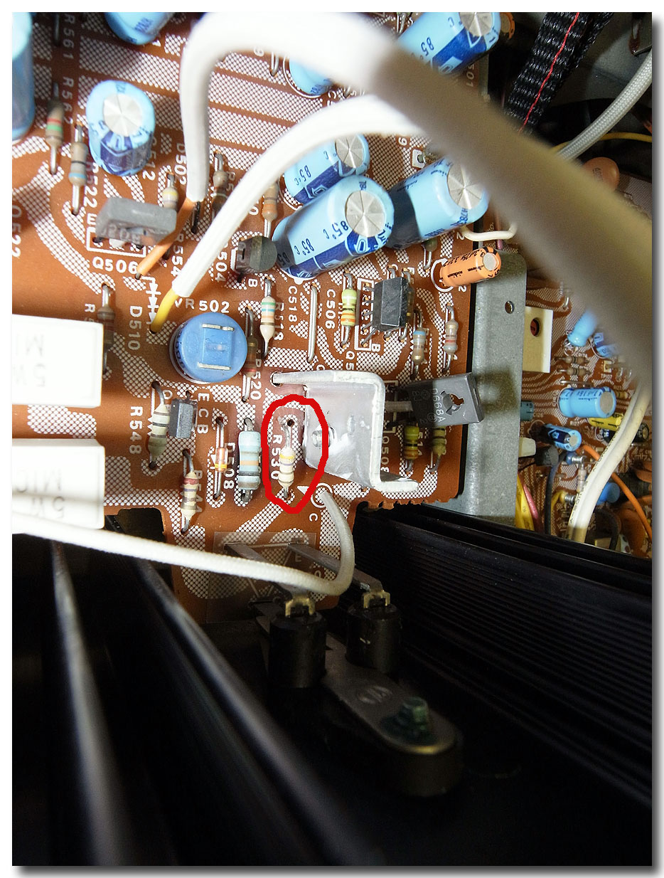
Did not try to take out the output transistors yet - they are kinda hard to get to - looks like I will have to lift the whole board out to get to the screws that hold them. Funny enough, those resistors I thought tested bad, - I re-tested and now they seem to work. I think I will go over all of them again, just to make sure. Let me know what else I can do/test. I will most likely have some time tomorrow and/or day after to play with this. Thanks!
Turkey day and shopping days are done with, so I can start focusing on this. I got my de-soldering pump and braid, and even looked at all the circled by you spots, fixed some up, now they look cleaner. No change as far as distortion goes. So, what should I tackle next? I did look at the link about testing transistors.
Did not try to take out the output transistors yet - they are kinda hard to get to - looks like I will have to lift the whole board out to get to the screws that hold them. Funny enough, those resistors I thought tested bad, - I re-tested and now they seem to work. I think I will go over all of them again, just to make sure. Let me know what else I can do/test. I will most likely have some time tomorrow and/or day after to play with this. Thanks!