Need help wiring a Dummy load

Kingbleu

Well-Known Member
I want to make a dummy load so I can work on equipment and not blow my eardrums out or wake up my kids late at night. I have two 8ohm 200 watt resistors that I mounted on heatsinks and put in a chasis. This works great and was easy to wire but I want to add a switch so that I can hear the sine wave in certain situations. I need help with wiring up the switch and even what switch to use. Is there a schematic or wiring diagram or could someone walk me through this. Also is there a certain type of switch? I have been trying different wiring combinations with no luck. I was thinking maybe I'm using the wrong switch.
 
Not sure what you are trying to accomplish here. What do you want to test while the dummy load is connected? Do you want to listen to the output with full power thru the dummy load? Does your equipment have a headphone output? why not use this?
Or you can wire up your own headphone output by putting a 100 ohm or more resistance in series with the speaker output. Or most consumer equipment has A-B speaker switch, you can connect to that.
 
I solved this problem by adding a couple of small single-ended tube output transformers with their primaries across the dummy loads. The secondary cold sides can be tied in common to a headphone jack without affecting amplifier load isolation --- so you can still test amps that don't allow a common ground connection at the loads. I believe the OPTs were designed for use with 6AQ5 output tubes, which makes nominal primary impedance around 5K ohms, but it will be much greater with typical headphone loads instead of speakers.
 
Easy, hook up the dummy loads to your amp and headphones to your unit (cheap ones). Make sure to turn down the volume when you connect the headphones (that's why cheap ones are the best since you'll forget).
 
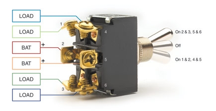
If you want to use speakers then a DPDT (double pole, double throw) switch is what you need. They look like this:
dpdt-on-off-on-jpg.jpg

Some have a center off position and some don't. Your application is better if you do not have a center off.

Here is how to wire them up:

Note that there are 6 terminals. You will be using 3 terminals for each of the stereo channels. The center terminal on each side goes to the HOT terminal on the speaker output of the amp. The top terminal on each side goes to the hot terminal of the speaker. The bottom terminal goes to one of the terminals of each resistor.

That accounts for half the circuit. The other have is this:

Connect the minus terminal of the right speaker, the 2nd lead on the right channel resistor and the common or minus therminal of the right channel of the amp together. You are connecting all three of these points together. Do the same for the left. Do NOT connect right and left together.

Shelly_D
 
Last edited:
Now, having given you the information on how to wire up an either or switch for your setup I have ask you, are you qualified to work on your gear? So you know how to be safe doing it? This is very basic stuff, and if you need help figuring this out, I worry about your knowledge level and your safety knowledge.

Shelly_D
 
When using a switch on a tube amplifier a common safety practice is to wire a moderate resistor, typically about 470 Ω, resistor across the speaker output to prevent arcing if no load is connected. (NB: 8 Ω || 470 Ω = 7.9 Ω, so the nominal impedance is unaffected. Anything in this range is going to be fine and not affect the reflected impedance through the output transformer that is seen by the output tube.)

Switches come as make-before-break and break-before-make to avoid having an open circuit. Solid state does not care about load as long as it is above zero Ω.

Adding flyback diodes is even better, but for some reason tube amplifier owners disparage any silicon, even when it is not in the audio path and used for protective purposes.
 
If you want to use speakers then a DPDT (double pole, double throw) switch is what you need. They look like this:
dpdt-on-off-on-jpg.jpg

Some have a center off position and some don't. Your application is better if you do not have a center off.

Here is how to wire them up:

Note that there are 6 terminals. You will be using 3 terminals for each of the stereo channels. The center terminal on each side goes to the HOT terminal on the speaker output of the amp. The top terminal on each side goes to the hot terminal of the speaker. The bottom terminal goes to one of the terminals of each resistor.

That accounts for half the circuit. The other have is this:

Connect the minus terminal of the right speaker, the 2nd lead on the right channel resistor and the common or minus therminal of the right channel of the amp together. You are connecting all three of these points together. Do the same for the left. Do NOT connect right and left together.

Shelly_D

Thanks Shelly that's exactly what I was looking for. It was hard for me to explain what I was trying to accomplish but thank you for reading between the lines. I finished wiring up my dummy load and ended up wiring two switches one for each channel. It came out looking really cool because I had a boat anchor (an old Fisher BA-6000) that I gutted. I used the Fisher's heat sinks and mounted the 200 watt resistors to them and used the Fishers speaker terminals which was very convenient. It would be cool if I could make use of the level meters like having them move in relation to the sound level but I'm not there yet and although it would be cool it is unnecessary.

Shelly I totally understanding your concern for my safety and if I am qualified to work on equipment especially given that I needed help with something as basic as a switch. In regards to that all I can say is that I have done one full restoration on a Fisher X-1000 which is documented here on AudioKarma and I am getting ready for a full restoration of my Pioneer SX-1250. Everything I know was self taught or learned here on audiokarma or youtube. It has taken several years but I have finally acquired enough test equipment to put on the bench ie. oscilloscope, function generator, dim bulb tester, ect...


Thanks to everyone who commented to my post.

P.S. I just bought a Function Generator a Circuit Mate FG2
 
Hi Kingbleu, do you have a picture of you dummy load, wired and set up??? I would love to see it

Pat
 
If you are switching when the amplifier is live you should ensure a load is always present, so make-before-break switches would be appropriate.
 
What I do is to connect a small speaker cabinet in series with a 500-1000 Ohm resistor.Then, connect the speaker across the load. This limits the volume down greatly but allows you to hear it without it getting loud.
 
would this not be of concern with the possible surge ?
If you are switching when the amplifier is live you should ensure a load is always present, so make-before-break switches would be appropriate.
Make-before-break: In a switching device, a configuration in which the new connection path is established before the previous contacts are opened.
 
would this not be of concern with the possible surge ? Make-before-break: In a switching device, a configuration in which the new connection path is established before the previous contacts are opened.

I don't know what you mean by "surge".

The OP wants to switch between speakers and a dummy load. If the switching is done hot, then the output transformers are unloaded at some point. That can cause arcing and destroy the output transformers and output tubes, possibly other bits.
 
I don't know what you mean by "surge".

The OP wants to switch between speakers and a dummy load. If the switching is done hot, then the output transformers are unloaded at some point. That can cause arcing and destroy the output transformers and output tubes, possibly other bits.
sorry i was thinking solid state ..at one moment the load might be very low then back up high or the other way too . would this not cause some sort of a surge ?
 
sorry i was thinking solid state ..at one moment the load might be very low then back up high or the other way too . would this not cause some sort of a surge ?

No surge risk. The impedance of a speaker constantly changes and the nominal value is a convenient fiction and shorthand.

So 8 to 4 Ω for the brief instant of switching (or even longer) is perfectly fine, especially with tubes which do not care. Certainly distortion, but without risk of damage.
 
Back
Top Bottom